CBEND
Bulk Data Entry Defines a curved beam or pipe element of the structural model.
Format
| (1) | (2) | (3) | (4) | (5) | (6) | (7) | (8) | (9) | (10) |
|---|---|---|---|---|---|---|---|---|---|
| CBEND | EID | PID | GA | GB | X1 | X2 | X3 | GEOM |
Alternate Format
| (1) | (2) | (3) | (4) | (5) | (6) | (7) | (8) | (9) | (10) |
|---|---|---|---|---|---|---|---|---|---|
| CBEND | EID | PID | GA | GB | G0 | GEOM |
Example 1
| (1) | (2) | (3) | (4) | (5) | (6) | (7) | (8) | (9) | (10) |
|---|---|---|---|---|---|---|---|---|---|
| CBEND | 1 | 2 | 10 | 11 | 3.22 | -4.62 | 1.35 | 3 |
Example 2
| (1) | (2) | (3) | (4) | (5) | (6) | (7) | (8) | (9) | (10) |
|---|---|---|---|---|---|---|---|---|---|
| CBEND | 1 | 2 | 10 | 11 | 15 | 4 |
Definitions
| Field | Contents | SI Unit Example |
|---|---|---|
| EID | Unique element
identification number. No default (Integer > 0) |
|
| PID | PBEND property entry identification
number.
Default = EID (Integer > 0 or <String>) |
|
| GA, GB | Grid point
identification numbers of connection points. No default (Integer > 0; GA ≠ GB) |
|
| X1, X2, X3 | Components of vector
v, at end A, parallel to the components of the basic coordinate
system, to determine (with the vector from end A to end B) the
orientation of the element coordinate system for the bend
element. No default (Real) |
|
| G0 | Grid point identification number to optionally supply X1, X2, X3. The direction of the orientation vector is GA to G0 (See Figure 1). | |
| GEOM | Flag to select the
geometry specification of the bend element. No default (1≤ Integer ≤ 4) |
Comments
- Element identification numbers must be unique with respect to all other element identification numbers.
- String-based labels allow for easier visual identification of properties, including when being referenced by other cards (for example, the PID field of elements). For more details, refer to String Label Based Input File in the Bulk Data Input File topic.
- If X1/G0 is a positive integer and X2 and X3 are blank, G0 is used to orient the element. Otherwise, X1, X2, and X3 are used.
- G0 ≠ GA or GB.
- You can define the geometry of the
CBEND element in the following ways:
GEOM Geometry Comments 1 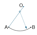
The segment AO (or AO extension or vector v) defines the radial direction of the arc. The arc center lies on this segment. Given this radial vector and grid points A and B, OptiStruct determines the arc center, radius and angle.
2 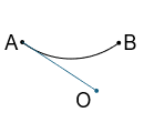
The segment AO (or vector v) defines the tangent vector of the arc at endpoint A. The arc AB and point O (or vector v) lie on the same side of the half-plane defined by chord AB. Given this tangent vector and grid points A and B, OptiStruct determines the arc center, radius and angle.
3 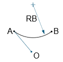
The PBEND card defines the arc radius RB. Grid points A, B and O (or vector v) define the plane of curvature. The arc center and point O (or vector v) lie on opposite half-planes with respect to the chord AB. Given RB, grid points A and B, and the curvature plane, OptiStruct determines the arc center and angle.
4 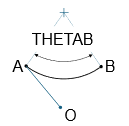
The PBEND card defines the arc angle THETAB. Grid points A, B, and O (or vector v) define the plane of curvature. The arc center and point O (or vector v) lie on opposite half-planes with respect to the chord AB. Given THETAB, grid points A and B and the curvature plane, OptiStruct determines the arc center and radius.
- In all GEOM options, the CBEND element is well defined only if 0° < THETAB < 180°.
- The stiffness matrix of CBEND element considers bending, extension, shear, and torsional effects.
- Only the coupled mass matrix option is available for the CBEND element. For the consistent mass matrix, the effects of shear deformation are neglected.
- CBEND currently supports the following types of
linear analysis and output in .*h3d format:
DISPLACEMENT (ROTA) ELFORCE (DIRECT) STRAIN STRESS Linear Static Analysis ✓ ✓ ✓ ✓ Normal Modes Analysis ✓ ✓ ✓ ✓ Frequency Response Analysis (Direct & Modal) ✓ ✓ ✓ ✓ Random Response Analysis (10) ✓ ✓ ✓ ✓ Linear Transient Analysis (Direct & Modal) ✓ ✓ ✓ ✓ - For random response analysis, CBEND supports the following *.h3d output: PSD Rotations, PSD Displacements, PSD Element Strains, PSD Element Stresses, and PSD Element Forces.
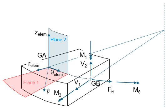
- In the *.h3d file, the Shear Plane-1, Bending Plane-1 and Shear Plane-2, Bending Plane-2 force results are associated with Plane-1 and Plane-2 respectively (see Figure 1). Figure 2 illustrates the positive direction convention for CBEND internal forces and moments.
- Strain, stress, and element force results are output in the element coordinate system in H3D format (Figure 2).
- CBEND does not
currently support the following forms of loading: thermal
(TEMP), gravity (GRAV),
centrifugal (RFORCE), concentrated or distributed loads
(PLOAD1).
Figure 1. CBEND Element Coordinate System 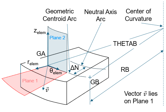
Figure 2. Direction of Internal Forces and Moments for CBEND Entry