
SECTION
Bulk Data Entry Defines a user-defined cross-section based on a specific face of the model.
The section is determined through a set of Grid points and the face is specified by a set of elements. The face is interpreted as the side of the Grid point set not containing the specified elements.
Format
| (1) | (2) | (3) | (4) | (5) | (6) | (7) | (8) | (9) | (10) |
|---|---|---|---|---|---|---|---|---|---|
| SECTION | SID | LABEL | GSID | ESID | RSID | CID | GID | STYPE |
Definitions
| Field | Contents | SI Unit Example |
|---|---|---|
| SID | Set identification number
of the section. No default (Integer) |
|
| LABEL | The section name
associated with the defined section. No default (Character string) |
|
| GSID | Set identification number
of a SET of GRID points that
defines the geometry of the section. 2 No default (Integer > 0) |
|
| ESID | Set identification number
of a SET of elements
(TYPE=ELEM) that defines the
face of the section. 2 No default (Integer > 0) |
|
| RSID | Set identification number
of a SET of rigid elements
(TYPE=RIGID) that defines
the face of the section. 2 No default (Integer > 0) |
|
| CID | Coordinate system
identification number of the coordinate system into which the forces
and moments are resolved. 7
(LOCAL or Integer ≥ 0) |
|
| GID | Grid point identification
number of the grid about which the moments are calculated.
Default = <Geometric Centroid of the Section> |
|
| STYPE | Identifies the type of
section that is generated using this entry.
|
Comments
- The SECTION entry can be used to define a face of the cross-section on which the forces/moments are calculated as a response in analysis and optimization runs via RTYPE=RESFORCE (on the DRESP1 entry). In such cases, Grid Point Forces or Moments are added at each GRID specified within the grid set (GSID). The effect of all elements on the grid points (GSID) is considered in the calculation of the response except the elements specified via ESID. The SECTION entry can also be used for Power flow and Mechanical intensity calculations. For more information regarding Power flow calculations, refer to the POWERFLOW I/O Options Entry. For the Power flow and mechanical intensity calculations, only the GSID, ESID, and STYPE fields are required. The other fields are ignored if input.
- The section is determined through a set of
grid points and the particular face is specified by a set of elements. The face
is interpreted as the side of the grid point set NOT containing the specified
elements (Figure 1 through Figure 3). This is similarly applicable to RSID
(rigid element set).
Figure 1. Defining the SECTION for the RESFORCE Response 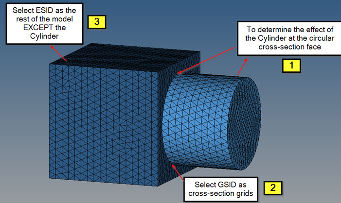
Figure 2. Selecting the GSID Set 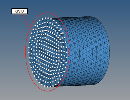
Figure 3. Selecting the Corresponding ESID 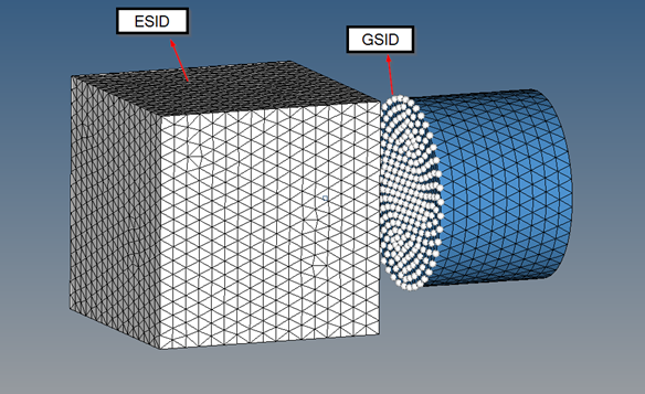
- The default GID is the
geometric center of the cross-section. For example, in a shell model, if the
cross-section is tapered (Figure 4), the geometric center is automatically
updated (if the GID field is blank).
Figure 4. Geometric Center via GID=Default 
- For Section property, if coordinate system is defined, then the properties are calculated in the defined system. If no coordinate system is defined, the basic system is used.
- For Section property, currently only beam, bar, shells and solid elements are supported. Offsets are taken into account, and Shear center is currently not calculated.
- SECTION is automatically created for both 1D and 3D pretension bolt section. For this case, CID is LOCAL and GID is CENT.
- In cases when the local coordinate system from LOCAL cannot be uniquely determined, a warning will be printed. In such cases, it is recommended to use a user-defined coordinate system. The X-axis of this user-defined coordinate system must be normal to the cross-section.
- This feature is supported for analysis, as well as optimization.
- For a special case in which the SECTION only contains one grid and one beam/rod element, then its local X-axis is aligned with that element. This applies to both internally created sections (like 1D bolt pretension sections) or a user-defined SECTION with the same characteristics. Additionally, for this special case, the Y-axis is determined by projecting the global Y-axis on to the plane orthogonal to the local X-axis.
- Information about both the user-defined SECTIONs and internally generated sections are output to the OPTI format .secres file and the .out file by default. The section force and moment result output can be controlled using the RESULTANT I/O Option.
- Heat flow output across sections of the model is now available via the RESULTANT I/O Option. The sections in the model for which output is requested should be defined via the SECTION Bulk Data Entry, with the STYPE field set to HEAT. For Heat flow output in Linear and Nonlinear Steady State Heat Transfer analysis, the presence of the SECTION entry is sufficient (RESULTANT is the default). For Linear and Nonlinear Transient Heat Transfer Analysis, both the SECTION entry and the RESULTANT entry are required for Heat flow output. Heat flow results are output in H3D and .secres files.
- Current flow output across sections of the model is now available via the RESULTANT I/O entry. The sections in the model for which output is requested should be defined via the SECTION Bulk Data Entry, with the STYPE field set to ELEC. For Current flow output in Steady State Electrical analysis, the presence of the SECTION entry is sufficient (RESULTANT is default). For Multi-Steady Electrical Analysis, both the SECTION entry and the RESULTANT entry are required for Current flow output. Current flow results are output in H3D and .secres files.