Bulk Data Entry Defines the properties of a beam element by cross-sectional
dimensions that are used to create beam elements via the CBEAM
entry.
Format
(1)
(2)
(3)
(4)
(5)
(6)
(7)
(8)
(9)
(10)
PBEAML
PID
MID
GROUP
TYPE/
NAME
ND
DIM1(A)
DIM2(A)
etc
NSM(A)
SO(1)
X(1)/
XB
DIM1(1)
DIM2(1)
etc
NSM(1)
etc
SO(B)
X(B)/
XB
DIM1(B)
DIM2(B)
etc
NSM(B)
* The format of this Bulk Data Entry is somewhat unusual as the field locations can vary
depending on the number of dimensions used to define the cross-section.
Optional continuation line for cross section integration (section type BAR & ROD
only):
(1)
(2)
(3)
(4)
(5)
(6)
(7)
(8)
(9)
(10)
+
INT
Q_ORDER
Q_ORDER2
Example
(1)
(2)
(3)
(4)
(5)
(6)
(7)
(8)
(9)
(10)
PBEAML
99
21
T
12.
14.8
2.5
26.
NO
0.4
6.
7.
1.2
2.6
YES
0.6
6.
7.8
5.6
2.3
YES
Definitions
Field
Contents
SI Unit Example
PID
Unique simple beam property
identification.
Integer
Specifies an identification number for this property.
<String>
Specifies a user-defined string label for this property. 2
Specifies a user-defined material identification string.
No default (Integer > 0 or <String>)
GROUP
Indicates if an arbitrary beam section
definition is to be used. Refer to Arbitrary Beam Section Definition in the User Guide.
If the value of this field is HYPRBEAM, the following field is
NAME; otherwise it is TYPE.
Default =
blank (blank or HYPRBEAM)
TYPE
Cross-section shape. When
GROUP field is blank, this field is
TYPE.
No default (BAR, BOX,
BOX1, CHAN, CHAN1,
CHAN2, CROSS, H,
HAT, HEXA, I,
I1, L, ROD,
T, T1, T2,
TUBE, or Z)
NAME
Name of arbitrary beam section
definition. Refer to Arbitrary Beam Section Definition in the
User Guide. When the value of GROUP is
HYPRBEAM, this field is NAME.
No default
(Character string)
ND
Number of dimensions used to specify the
Cross-section shape. This is required when the value of the GROUP
field is HYPRBEAM. ND represents the total
number of dimensions used to define an Arbitrary Beam Section.
Default =
blank
DIMi(A)
Cross-section dimensions at end A.
No
default (Real > 0.0)
NSM(A)
Nonstructural mass per unit length at
end A.
Default = 0.0 (Real)
SO(#)
Stress output request option for
intermediate station #.
Stress output is not supported for intermediate stations
so this field must be set to NO.
X(#)/XB
Distance from end A to intermediate
station # in the element coordinate system, divided by the length of the
element.
Default = 1.0 (Real > 0.0)
DIMi(#)
Cross-section dimensions at intermediate
station #.
(Real > 0.0)
NSM(#)
Nonstructural mass per unit length at
intermediate station #.
Default = 0.0 (Real)
SO(B)
Stress output request option for end
B.
YES (Default)
NO
X(B)/XB
Distance form end A to end B in the
element coordinate system, divided by the length of the element.
This must be
1.0
DIMi(B)
Cross-section dimensions at end
B.
(Real > 0.0)
NSM(B)
Nonstructural mass per unit length at
end B.
Default = 0.0 (Real)
INT
Continuation line flag for activating
integrated beam. 10
Q_ORDER
Defines the quadrature order for
determination of the number of sub-sections of integrated beam.
For structural problems,
MID may reference only a MAT1
material entry. For heat transfer problems, MID may reference only a
MAT4 material entry. In implicit analysis,
MID can reference MAT1 and MAT4
in combination with adiabatic analysis.
String based labels allow for easier visual
identification of properties, including when being referenced by other cards. (For
example, the PID field of elements). For more details, refer to String Label Based Input File in the Bulk Data
Input File.
Up to eleven stations are allowed (end A and
B, and nine intermediate stations #).
The cross-sectional properties, shear
flexibility factors, and stress recovery points (C, D, E, and F) are computed using the
TYPE and DIMi as shown below. The element
coordinate system is located at the shear center.
Figure 1. TYPE = BAR
Figure 2. TYPE = BOX
Figure 3. TYPE = BOX1
Figure 4. TYPE = CHAN
Figure 5. TYPE = CHAN1
Figure 6. TYPE = CHAN2
Figure 7. TYPE = CROSS
Figure 8. TYPE = H
Figure 9. TYPE = HAT
Figure 10. TYPE = HEXA
Figure 11. TYPE = I
Figure 12. TYPE = I1
Figure 13. TYPE = L
Figure 14. TYPE = ROD
Figure 15. TYPE = T
Figure 16. TYPE = T1
Figure 17. TYPE = T2
Figure 18. TYPE = TUBE
Figure 19. TYPE = Z
For PBEAML entries with
more than one section, an equivalent PBEAM entry is derived. An echo
request will cause a printout of the derived PBEAM.
Stress recovery is only allowed at end A and
end B. Stress recovery at intermediate stations is not supported.
For
TYPE=ROD, if
X(1)/XB is equal to 1.0, then the
DIM(1)A references the radius of the beam at end A and
DIM(1)B references the radius of the beam at end B and there are no
intermediate stations. This element is a tapered beam formulation, and averaging is not
used to determine the average radius of the beam. Instead, the true tapered beam
formulation is used with the given dimensions. The true tapered beam formulation is only
available for TYPE=ROD.Figure 20.
DIMi and
NSM have to be specified fully on station A. On station B, blank
means that the dimensions are the same as at A. On other stations, it is a linear
interpolation between A and B.
The NSM specified at end A
is the default value for NSM at end B. The default for all other
stations is a linear interpolation between end A and end B. So, for a constant
NSM over the length of the beam, only NSM at end A
is required.
The mass of the element is calculated as:
If the NSM value is different in different
stations, it is averaged over all the stations and the average is used in the element
calculation.
The integrated beam is supported only in
nonlinear implicit and explicit analyses. Both elastic materials (MAT1)
and plastic materials (MAT1 and MATS1) are supported
in both implicit and explicit analyses. In implicit analysis, integrated beam also
supports the temperature-dependent material for elastic material property with the
MATT1 card, and temperature dependent stress-strain data for plastic
material using TABLEST within MATS1 card, which is
currently limited to hardening rules HR = 1, 2 or 3. The integrated
beam is automatically activated when MATS1 is referenced. The
integrated beam can be activated for MAT1 with the keyword
INT in the PBEAML continuation line.
The integrated beam formulation is currently available for
TYPE = ROD/BAR/I
sections. In this case, the beam is computed using cross-section integration. The
integration points are automatically distributed in the section according to the
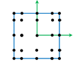
quadrature order and the type of the section. For BAR, the number of
integration points is Q_ORDER * Q_ORDER. In implicit analysis, some examples of
integration point distribution in beam cross sections based on the Q_ORDER value are
mentioned below.
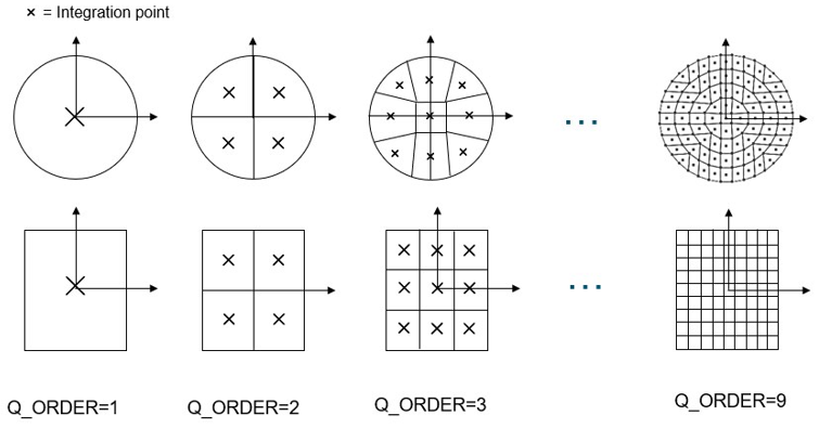
Implicit Analysis: ROD and BAR
Sections
In implicit analysis, the number of integration points is calculated only
based on Q_ORDER. By default, it is 4 for ROD, thus
16 integration points, and 5 for BAR, thus 25 integration points.Figure 21. Implicit Analysis ROD and BAR Section Integration Points
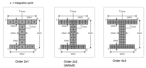
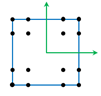
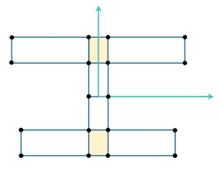
Implicit Analysis: I, L, and
TUBE Section
In implicit analysis, the number of integration
points for I-section is determined with Q_ORDER and
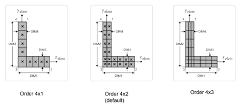
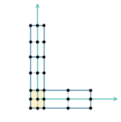
Q_ORDER2. By default it is 2x2, thus 32 integration points.Figure 22. Implicit Analysis I Section Integration Points Similarly, for L-section the default is 4x2, thus 20 integration
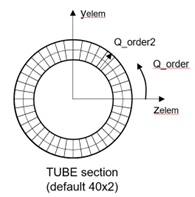
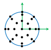
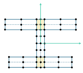
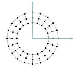
points. Figure 23. Implicit Analysis L Section Integration Points The TUBE section has a default of 40x2, thus 80 integration
points. Figure 24. Implicit Analysis TUBE Section. Default Q_ORDER = 40, Q_ORDER2 = 2
In explicit analysis, some examples of integration point distribution in
beam cross sections based on the Q_ORDER value are:
Explicit
Analysis: ROD and BAR sections
Figure 25. BAR Section Q_ORDER = 5
(Default)
Figure 26. BAR Section Q_ORDER = 4
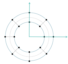
Figure 27. ROD Section Q_ORDER = 4
(Default)
Figure 28. ROD Section Q_ORDER = 5
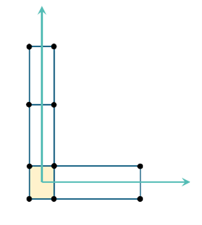
Explicit Analysis: I and L Sections
Sub-section
definition is similar to implicit analysis but the default value for
Q_ORDER is different.
Figure 29. I Section Order 2x2 (Default)
Figure 30. I Section Order 1x1
Figure 31. L Section Order 2x2 (Default
Figure 32. L Section Order 1x1
Explicit Analysis: TUBE Section
Sub-section
definition is also similar to implicit analysis with different default values for
Q_ORDER.
Figure 33. TUBE Section Order 20x2 (Default)
Figure 34. TUBE Section Order 8x1
The table below details the default
quadrature order (Q_ORDER and Q_ORDER2) and the
total number of integration point in beam sections in both implicit and explicit
analysis.
Section
Implicit Defaults Q_ORDER, Total number of integration points (max Q_ORDER
x Q_ORDER2)
Explicit Defaults Q_ORDER, Total number of integration points, (max Q_ORDER
x Q_ORDER2)
ROD
4x4, 16 (max 9)
4x4, 17 (max 5x5)
BAR
5x5, 25 (max 9)
5x5, 25 (max 5x5)
I-Section
2x2, 32 (max 9x9)
2x2, 51(max 5x5)
L-Section
4x2, 20 (max 9x9)
2x2, 27 (max 5x5)
TUBE
40x2, 80 (max 360x9)
20x2, 60 (max 40x5)
This card is represented as a property in
HyperMesh.