
CQAXI
Bulk Data Entry Defines a 2D axisymmetric quadrilateral cross-section ring element.
Format
| (1) | (2) | (3) | (4) | (5) | (6) | (7) | (8) | (9) | (10) |
|---|---|---|---|---|---|---|---|---|---|
| CQAXI | EID | PID | G1 | G2 | G3 | G4 | G5 | G6 | |
| G7 | G8 | Theta |
Example
| (1) | (2) | (3) | (4) | (5) | (6) | (7) | (8) | (9) | (10) |
|---|---|---|---|---|---|---|---|---|---|
| CQAXI | 111 | 2 | 31 | 74 | 75 | 32 | 51 | 52 | |
| 63 | 62 | 15.0 |
Definitions
| Field | Contents | SI Unit Example |
|---|---|---|
| EID | Unique element
identification number. No default (Integer > 0) |
|
| PID | A PAXI entry identification
number. Default = EID (Integer > 0) |
|
| GI | Identification numbers of
connected corner grid points. Corner grid points cannot be omitted. No default (Integers > 0, all unique) |
|
| Theta | Material orientation angle in
degrees. Default = 0.0 (Real) |
Comments
- Element identification numbers must be unique with respect to all other element identification numbers.
- The element grids numbering scheme is
controlled by
SYSSETTING,AXEGORD,0/1.
SYSSETTING,AXEGORD Corner Grid Points Edge Grid Points C1 C2 C3 C4 E1 E2 E3 E4 0 (default) G1 G3 G5 G7 G2 G4 G6 G8 1 G1 G2 G3 G4 G5 G6 G7 G8 - All the grid points must be in the x-y plane or in the x-z plane of the
basic coordinate system with x = r ≥ 0.
Corner grid points C1, C2, C3 and C4 must be present. The edge points E1, E2, E3 and E4 are optional. If any of the edge points are present, they all must be used.
Note that this information is consistent only for the default SYSSETTING,AXEGORD,0. If this is switched to 1, then the corresponding grid point references should be interpreted accordingly.
Figure 1. CQAXI Definition 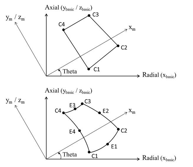
- The continuation line is optional.
- If the PAXI entry referenced in field 3 references a MAT3 entry, material properties and stresses are always given in the (xm, ym) or (xm, zm) coordinate system shown in Figure 1.
- A concentrated load (for example, the load specified on a
FORCE entry) at a grid Gi of this
element denotes that applied onto the circumference with radius of
Gi. For example, in order to apply a load of 200N/m on
the circumference at Gi which is located at a radius of 0.4m,
the magnitude of the load specified on the static load entry must
be:
- Axisymmetric elements are supported only for Linear Static, Nonlinear Static (small and large displacement) and Heat Transfer (linear and non-linear, steady-state, and transient) Analysis. Currently, axisymmetric elements are not supported for Inertia Relief Analysis in Large Displacement Nonlinear Analysis.
- Axisymmetric elements are supported only for size optimization (only material property – DVMREL1, DVMREL2) and shape optimization, using stress responses. Refer to DRESP1 - Static Stress/Strain Item Codes for more details.
- PARAM,AXI2DTOR,YES can be used to convert 2D axisymmetric elements
CQAXI and CTAXI in the model to
general axisymmetric elements CQAXIG and
CTAXIG, respectively, while PAXI is
considered as PAXIG, which allows the elements to have
torsional deformation about the axis-of-symmetry. Note: With this option, the elements may need additional constraints in the out-of-plane direction to eliminate rigid body motions. Currently this option is supported only for linear analyses (including static, dynamic and preloading analyses).