
SURF
Bulk Data Entry Defines a face of a shell or solid (3D solid, axisymmetric solid, or plane-strain solid) element as part of a surface.
Format
| (1) | (2) | (3) | (4) | (5) | (6) | (7) | (8) | (9) | (10) |
|---|---|---|---|---|---|---|---|---|---|
| SURF | SRFID | ELFACE | |||||||
| EID1 | GA1 | GB1 | NORMAL1 | ||||||
| EID2 | GA2 | GB2 | NORMAL2 | ||||||
| EID3 | etc. | etc. | etc. | ||||||
| etc. | etc. |
Alternative Format (faceted surface)
For a 3D space model: In this format, surface is represented as a collection of 3- or 4-noded polygons (facets). Each facet is defined by 3 or 4 GRID IDs.
| (1) | (2) | (3) | (4) | (5) | (6) | (7) | (8) | (9) | (10) |
|---|---|---|---|---|---|---|---|---|---|
| SURF | SRFID | FACE | |||||||
| GA1 | GB1 | GC1 | GD1 | ||||||
| GA2 | GB2 | GC2 | GD2 | ||||||
| GA3 | etc. | etc. | etc. | ||||||
| etc. | etc. |
Alternative Format (SET Format)
A surface may also be defined using a form of the SET Bulk Data Entry. With this approach, the surface is composed of all selected shell elements and the external faces of all selected solid elements; that is, those faces that are not connected to any other solid element faces in the model.
To use this format, the SURF keyword is used in place of the SET keyword and the TYPE must be ELEM. All methods for defining a set of type ELEM are valid for this form of surface definition. Refer to the SET Bulk Data Entry.
Definitions
| Field | Contents | SI Unit Example |
|---|---|---|
| SRFID | Surface identification number.
No default (Integer > 0 or <String>) |
|
| ELFACE | Flag indicating that the surface is composed of an element face. | |
| EID# | Shell or solid element identification
number. No default (Integer > 0) |
|
| GA# | Grid point identification number at the
corner of the desired face of a solid element. This field must be blank for shell elements. Default = blank (Integer > 0, blank) |
|
| GB# | Optional grid point identification
number. Used to identify face of solid elements. 1 Default = blank (Integer > 0, blank) |
|
| NORMAL | Identifies the normal direction for a
face of the surface. The normal of a face of a surface may be different from the
normal of the underlying elements.
|
|
| FACE | Flag indicating that the surface is composed of 3-noded or 4-noded polygons (facets) for a 3D space model, or, 2-noded line segments (facets) for a 2D space model. | |
| GA#, GB#, GC#, GD# | Grid point identification numbers at the
corners of the facet.
No default (Integer > 0) |
Comments
- GB is
used to identify faces of solid elements based on the following table:
For HEXA Elements Grid point identification number at a corner of the desired face that is diagonally opposite GA. PENTA elements Quad faces: Grid point identification number at a corner of the desired face that is diagonally opposite GA. Tria faces: Leave blank. TETRA elements Grid point identification number at the corner opposite the desired face. PYRA elements Quad faces: Leave blank Tria faces: GA and GB must specify the grids on the edge of the face that borders the quadrilateral face, and the grids must be ordered so that they define an inward normal using the right-hand rule. CQUAXI, CTAXI, CTRIAX6, CQPSTN, and CTPSTN elements GA and GB should specify the corner grids on the line segment. - For the “FACE” format, the normal direction of a
facet is defined as:
Figure 1. 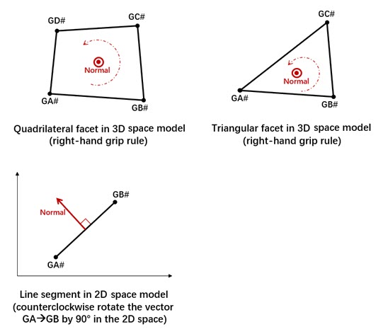
- ELIST is an
alternative to SET and SURF, but
ELIST is intended only to provide compatibility with Nastran decks. It is recommended to use
SURF/SET instead of ELIST.
Additionally,
- The SURF and SET entries may not be combined with ELIST entries to define damp elements.
- ELIST entries are internally converted to SET entries. If ELIST is referenced on a minimum of one MFLUID entry, then all MFLUID entries in a model must reference ELIST entries. In such cases, if an MFLUID entry references a particular Set Identification Number (<SID>) to define WSURF1/WSURF2 fields without a corresponding ELIST,<SID> in the model, then OptiStruct will not search for a SET/SURF,<SID>.
- String based labels allow for easier visual identification, including when being referenced by other entries. For more details, refer to String Label Based Input File.
- This card is represented as a contact surface in HyperMesh.