RSSCON1
Bulk Data Entry Defines a set of constraints for shell-to-solid connection on surfaces.
Format
| (1) | (2) | (3) | (4) | (5) | (6) | (7) | (8) | (9) | (10) |
|---|---|---|---|---|---|---|---|---|---|
| RSSCON1 | RBID | PTOL | Val(PTOL) | INFL | Val(INFL) | ||||
| + | SHL1 | SLD1 | |||||||
| + | SHL2 | SLD2 | |||||||
| + | etc. |
Example
| (1) | (2) | (3) | (4) | (5) | (6) | (7) | (8) | (9) | (10) |
|---|---|---|---|---|---|---|---|---|---|
| RSSCON1 | 20 | INFL | 0.5 | ||||||
| + | 2 | 3 | |||||||
| + | 2 | 4 |
Definitions
| Field | Contents | SI Unit Example |
|---|---|---|
| RBID | Unique element identification number. No default (Integer > 0) |
|
| PTOL | Position tolerance, followed by a real value,
Val(PTOL). By default, this value will be
determined automatically. 5 Default = blank (Characters) |
|
| Val(PTOL) | Position tolerance of the shell-to-solid distance within
which a shell grid is included in the shell-to-solid
constraints. (Real > 0.0) |
|
| INFL | Influence radius, followed by a real value,
Val(INFL). If INFL is
not present, the default influence radius will be half the shell
thickness. Default = blank (Characters) |
|
| Val(INFL) | The radius of the cylindrical influence region around the
shell edge within which a solid grid is included in the
shell-to-solid connection. 6 (Real > 0.0) |
|
| SHLi | Shell surface/set identification number of the i-th
shell-solid pair. SURF format of type
ELFACE and SURF/SET format of type
ELEM are supported. No default (Integer > 0) |
|
| SLDi | Solid surface/set identification number of the i-th
shell-solid pair. SURF format of type
ELFACE and SURF/SET format of type
ELEM are supported. No default (Integer > 0) |
Comments
- RSSCON1 supports both 1st and 2nd order element faces.
- RSSCON1 supports linear and nonlinear analyses. It is typically supported for all analysis types for which RBE3 elements are supported.
- The basic assumption is that the geometry of the solid surface is generally perpendicular to the shell.
- The mesh pairs on the shell-to-solid interface are not required to be matching or aligned, although aligned mesh would help on accuracy, for example, the solid surface can be composed of arbitrary triangles and quadrilaterals.
- If PTOL is not present, the default position tolerance will be calculated as 5% of the averaged characteristic length of a set of nearest solid faces. For cases where a lenient position tolerance is needed, it is recommended that the value is set such that only the outer shell edge closest to the solid surface is included, that is Val(PTOL) should be greater than the distance to the closest edge grids and smaller than the second closest layer of shell nodes to the solid surface.
- OptiStruct searches for solid nodes to be included by
segments, and each segment is enclosed by two corner points on the same edge
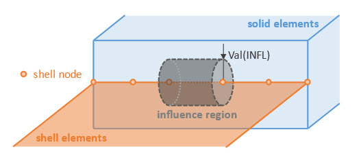
of a shell element. The influence region is a cylindrical volume for each
segment on the shell edge, whose radius is Val(INFL), as
shown in Figure 1. If PTOL is not
present, the default influence radius will be half the shell thickness.
Figure 1. Influence region at a segment on the shell edge 
- RSSCON1 will be internally converted to a set of RBE3 elements, with shell grids being dependent grids and solid grids being independent. The weighting factor of each independent grid is determined automatically, which reflects a measure of the grid tributary area lying in the influence region. Shell nodes referenced by RSSCON1 cannot be referenced by another RSSCON1 or also be assigned dependent by another rigid element or by a multi-point constraint.
- All the nodes of a solid face are included in the solid-to-shell constraints even if the face lies partially in the influence region, but the nodal weighting factors contributed from the nodal tributary areas of this face will be multiplied by a face participation factor to reduce the influence of the face in the constraint.
- On the solid side, if the geometric feature angle (along the shell edge) of adjacent faces changes drastically, for example, greater than or equal to 90 degrees, it is recommended that the solid side is split into two surface definitions which are to be paired with the shell side in 2 continuation lines.
- Shell elements with offset are supported in shell-to-solid connection.
- It is recommended that local stresses and strains are evaluated at least one layer of elements away from the shell-to-solid interface.
- RSSCON1 should be chosen over RSSCON for most situations of shell to solid connection. RSSCON1 works well even if the internally generated RBE3 elements needs to cover multiple layers of solids. Such a situation may occur if the thickness of shells is large enough that the connection needs to include multiple layers of solid elements. RSSCON1 is supported for large displacement nonlinear analysis, while RSSCON is not. The only case where RSSCON may provide better performance is when a single layer of solid elements aligns perfectly with shell elements. In this case, RSSCON1 still provides generally acceptable results and RSSCON Bulk Data Entries must be setup manually for each pair of shell element and solid element facets.