In the source diagram on the host computer, you insert and configure a Target Interface block for communicating with the generated code running on the target. A Target Interface block is a mirror image of the compound block containing the simulated controller. It has the same number and type of input and output connectors; however, it only includes:
•The executable code file name (OUT or ELF file)
•Settings for timing options
•CPU Utilization
Signals applied to the Target Interface inputs travel from the diagram to the executable code running on the target via the HotLink (JTAG, serial, Ethernet).
The executable code responds to these inputs and produces outputs that travel from the target to the diagram through the Target Interface block outputs.
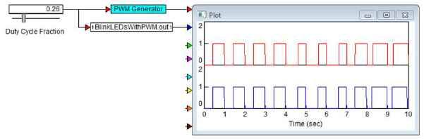
A source diagram using the Target Interface block is shown below.
Here, the simulated controller (PWM Generator) and the Target Interface block (BlinkLEDsWithPWM.out) are fed into a plot block. A slider provides the duty cycle fraction input signal to the simulated controller and the Target Interface block. When you simulate the diagram, both the simulated controller and the executable code on the target begin executing. After processing the input signal, both the simulated controller and the executable code produce output signals that are made available to the source diagram through the output connectors on the compound block and the Target Interface block. These outputs are sent to the plot block allowing one to compare the two responses.
You can use $isCodeGen to detect whether you are generating code from a diagram or if you are simply simulating the diagram. Using this feature allows the same diagram to be used for SIL, PIL, and HIL.