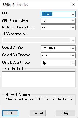
Target Category: Cortex M3
The ARM Cortex M3 Config block lets you configure settings for the ARM Cortex M3.

Clock Source: Chooses the hardware source for the system clock.
Ctrl Clk Count Mode: Chooses the count mode for the PWM-based control clock. If the PWM is also used as an output peripheral, this setting must match the setting of the PWM block in the diagram.
Control Clk Prescale: Chooses the prescale factor for the PWM-based control clock. If the PWM is also used as an output peripheral, this setting must match the setting of the PWM block in the diagram.
Control Clk Src: Sets the periodic sampling interrupt source for the main control loop in Embed.
CPU: Specifies the CPU types. It is important to select the exact CPU type for the specified target.
CPU Speed: Indicates the speed of the CPU.
Enable Interactive Peripheral Mode: Causes a pre-configured OUT file (whose only task is to read and write peripheral data) to be downloaded to the target. All ADC, Quadrature Encoder, PWM, and GPIO blocks in the diagram read and write actual values from the on-chip peripherals at the speed of the JTAG (~150 Hz).
When enabled, Enable Interactive Peripheral Mode inhibits using the Target Interface block to perform HIL simulations.
EPWM Interrupt Event: Chooses PWM event if PWM interrupt is selected as the Control Clk Src.
HSPCLK: Drives the ADC sample timer.
JTAG Connection: Indicates the JTAG driver to be used for HotLink communication.
LSPCLK: Drives the serial and SPI ports.
Multiple of Crystal Freq: Indicates the multiple of crystal frequency.
Preload Out File: Lets you debug the slave core while loading your application in the master core.
|
|
F2812 |
F2812 |
|
Encoder Channel A |
QEP1 |
QEP3 |
|
Encoder Channel B |
QEP2 |
QEP4 |
|
Encoder Index |
CAP3 |
CAP5 |
Use Custom Linker Cmd File: Overrides using the default linker command file. When activated, you must enter the path to your custom linker command file in the corresponding text box. If there are spaces in the path, enclose the path in double quotation marks.