Target Category: STM32
Target Sub-Category: PWM
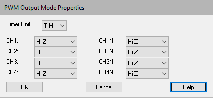
Description: Each STM32 motor control timer (timers 1, 8, 20) has four PWM outputs with optional complementary outputs with deadband. Normally, however, only three are used for 3-phase motor control. The Set PWM Mode block lets you set the output mode of each pin. There are four output modes:
•HiZ: High impedance, or unconnected
•Force 0: Forced low to ground
•Force 1: Forced on to Vcc
•PWM: Controlled by PWM duty
This allows you to commute the phases of a BLDC motor based on Hall sensor input.

CH1-CH4: Specifies the output mode.
CH1N-CH4N: Specifies the output mode.
Timer Unit: Specifies the timer unit to be configured.
Example
This example uses six Set PWM Mode blocks, one for each Hall sensor value per electrical rotation. Note that the blocks have an enable pin, so they only execute if the input value is 1. The block face shows row 1=name, row 2 = setting of four main outputs, row 3 = setting of four complementary outputs. For any given Hall phase, the Set PWM Modeblock will configure the three motor phase half H-bridges so that 1 is off (0/0), 1 is tied to ground (0/1), and 1is modulated via PWM (pwm/pwm). The fourth column is hiZ/hiZ since it is unused.
