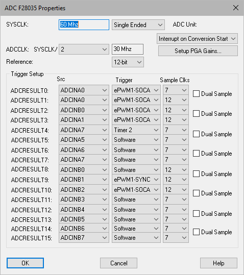
To configure the ADC trigger setup, you must first insert an F281X Config block in your diagram and set the CPU to your device. Only then can you access the ADC Config Properties dialog.
ADCCLK: Specifies the analog-to-digital converter clock.
Channel Sample Order: Specifies the order in which you sample the channels. Click New to specify a new sample order.
HCLK: Specifies the high-speed clock.
Sample Duration: Chooses the number of ADC clock ticks for a given ADC sample. High impedance inputs require longer samples. A recommended duration is 20 nsec.
Controls when to start sampling channels.
Cascade Sequence 1 and
2: Scans sequence 1 followed by sequence
2.
Sample Sequence 1 and 2 at the same time: Allows the simultaneous
sampling of the two sequences.
SYSCLK: Indicates the speed of the CPU clock.
Use Continuous Conversion: Enables the continuous conversion option in the hardware.
Use Full Scale Value = 1: Provides direct read of the ADC result register with no scaling. When activated, the value will range from 0 – 0.00007. When de-activated, Embed adds code to scale the result from 0 – 3.