Target Category: MSP430
Target Sub-Category: PWM
Description: The PWM block accepts scaled integer (fixed point) 1.16 input.
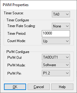
PWM Out: Chooses the pin on which the PWM appears.
PWM Pin: See Timer A and Timer B descriptions in the MSP430UM.PDF file supplied with this software.
PWM Mode: See Timer A and Timer B descriptions in the MSP430UM.PDF file supplied with this software.
Count Mode: Specify one of four modes: Hold, Up/Down, Up, and Continuous.
Timer Period: In conjunction with Timer Rate Scaling, determines the frequency of the PWM waveform. For example, if the base clock rate is 32 MHz and Timer Rate Scaling is 1/32, the effective clock rate is 1 MHz.
If Timer Period is set to be 10, then the output PWM frequency is 1/10 the effective clock rate of 1 MHz (100 kHz). However, this is a poor example since if Timer Period is set to be only 10, the output PWM frequency can only be varied in steps of 10%.).
Timer Rate Scaling: In conjunction with Timer Period, determines the base PWM frequency. Select from available fractional timer rate multipliers to reduce the timer rate. Fractional rates of up to 1/8th the basic rate are possible. See Texas Instruments documentation for more information.
Timer Source: Specifies the timer source. If you choose the same timer for each PWM, then you must also choose the same timer rate and timer period for each PWM. Check with your MSP430 part description for the number of PWM outputs that are available.