Target Category: Delfino, F280x, Piccolo
Target Sub-Category: PWM
Description: The ePWM block lets you configure the enhanced PWM unit. The dynamic phase input operates on the current scaled period.
The Duty Cycle input pins control the duty cycle of the PWM waveform. They are at scaled 1.16. The input value is multiplied by the PWM period and assigned to the PWM compare register to generate a fractional duty cycle. Thus, an input of 0.5 (fx1.16) yields a 50% duty cycle; an input of 0 yields 0% duty cycle; and an input of 0.99997 (the largest possible positive value in 1.16 notation) yields 100% duty cycle.
To mirror the input pins on the ePWM with the corresponding output pins on ePWM for Sim block, activate Use CMPC/CMPD, TBCTR=TBPHS on SYNCI pulse, Change Phase Dynamically, and Change Period Dynamically in the ePWM Properties dialog.
You can add an input pin that enables the unit externally. A corresponding output pin on the ePWM for Sim block is also present.
Interactive mode: In this mode, both Duty Cycle input pins are active; however, all parameters in the dialog are inactive except the PWM Unit parameter.
Additional information:
•How to generate 3-phase PWM for 3-phase inverter
•How to sync two PWM units 180o out of phase
•How to capture a PWM signal with eCAP block
•Texas Instruments SPRU791A document
EPWMA and EPWMB: Determines which events are translated into specific actions that produce the required waveforms at EPWMA and EPWMB. Actions are generated based on the following events:
Z: counter = 0
CMPA Up: counter = CA
during up count
CMPA Down: counter = CA during down count
CMPB
Up: counter = CB during up count
CMPB Down: counter = CB during
down count
P: counter = period
You can choose the following actions for any of the events:
X = Do nothing
0 = Force output to
0
1 = Force output to 1
T = Toggle output
Delay Mode: Indicates the deadband mode.
Falling Edge Delay Count: Indicates an independent value for falling edge delay.
Input Select: There are two inputs to the Deadband unit: PWMA and PWMB. These two inputs are DbA and DbB. They can be driven by any combination of PWMA and PWMB.
Polarity: Indicates the polarity for the specified deadband.
Rising Edge Delay Count: Indicates an independent value for rising edge delay.
Add Enable Pin: Adds an input pin that lets you enable or disable the unit externally.
Autoreset TZx Fault Source: Allows the reset of the fault on the next cycle of the PWM.
CBC TZx Fault Source: Enables a cycle-by-cycle trip zone fault and selects the pins that are used. The PWM is put in fault mode until the next cycle.
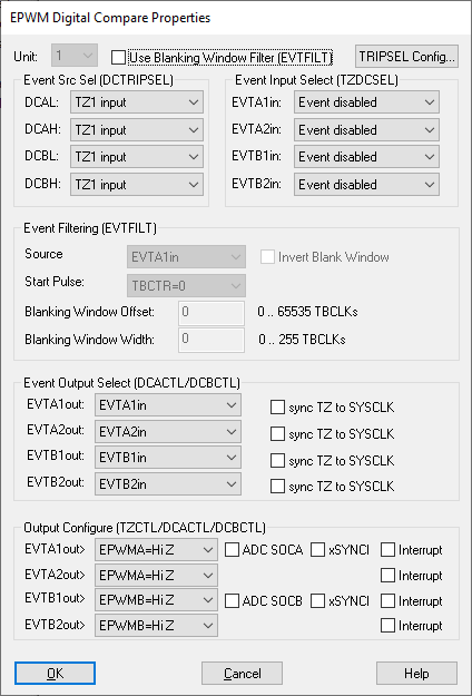
Digital Compare: Invokes the Digital Compare set up.
EPWMA Output on fault: Specifies the A response to the fault. Your choices are:
Fault Action Disabled: No response to the
fault
Forced High: Electrical conductance to 3 V
Forced
Low: Electrical conductance to ground (0 V)
High Impedance: No
electrical conductance on the A output
EPWMB Output on fault: Specifies the B response to the fault. Your choices are:
Fault Action Disabled: No response to the
fault
Forced High: Electrical conductance to 3 V
Forced
Low: Electrical conductance to ground (0 V)
High Impedance: No
electrical conductance on the A output
One Shot TZx Fault Source: Enables a one-shot trip zone fault and selects the pins that are used. The PWM is put in fault mode until code is executed to bring it back up.
PWM Unit: Specifies the unit to be configured.
Send Start ADC Conversion Pulse A: Indicates whether the ePWM unit should send a SOC A (start conversion on Pulse A) to the ADC unit.
Send Start ADC Conversion Pulse B: Indicates whether the ePWM unit should send a SOC B (start conversion on Pulse B) to the ADC unit.
Change Period Dynamically: Produces an external input pin (%Period (1.16)) that lets you specify a fractional value for the period on-the-fly. The external value will be multiplied by the period and assigned to the TBPRD (period) register. This allows you to dynamically modulate the PWM-based frequency.
Change Phase Dynamically: Produces an external input pin (%Phase (1.16)) that lets you specify a fractional value for the phase on-the-fly. The external value will be multiplied by the phase and assigned to the TBPHS (phase) register. This allows you to dynamically modulate the PWM-based frequency. To activate Change Phase Dynamically, you must also activate TBCTR=TBPHS on SYNCI pulse.
CMPA/B Load On: Selects condition to cause the CMPA/B register to be loaded.
Count Mode: Determines the counting mode. Typically, Up/Down is selected.
EPWMSYNCI Pin: Indicates the hardware pin supplying the EPWMSYNCI input pulse for unit 1.
EPWMSYNCO: Indicates the synchronizing signal sent from this unit to unit n+1.
Rate Scaling: Scales the timer source to a slower rate.
TBCTR=TBPHS on SYNCI pulse: The counter for this unit is assigned the value of the TBPHS (phase) register on occurrence of a SYNCI input pulse.
TBPHS (phase): Specifies an offset value added to the time-based counter on occurrence of the SYNCI input pulse.
Timer Period: Specifies the number of PWM clock ticks for one complete PWM waveform. The frequency of the PWM signal is determined as follows:
System-Clock-Frequency/Timer-Frequency = PWM-Frequency
For example, 150 MHz/150 = 1 MHz.
Use CMPC/CMPD: Enables compare C and compare D inputs that can be used to send synchronization pulses to the ADC or DMA unit.
Use High Res Timer: Enables the use of a high-resolution timer.