Solution
Introduction
Solution model setup approach offers to quickly simulate engineering behavior and make engineering decisions. Solution approach enables performing of structural, thermal, flow and Electromagnetics analysis and postprocess within a single environment. The single browser set up addresses the limitation of traditional SimLab where only single type of analysis being set up within database.
Check SimLab - Learning centre videos for more details on Model setup using Solution approach.
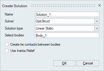
Dialog box
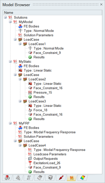
Browser
Features
- Multiple solutions can be defined for a model or selected bodies in a model to perform analysis.
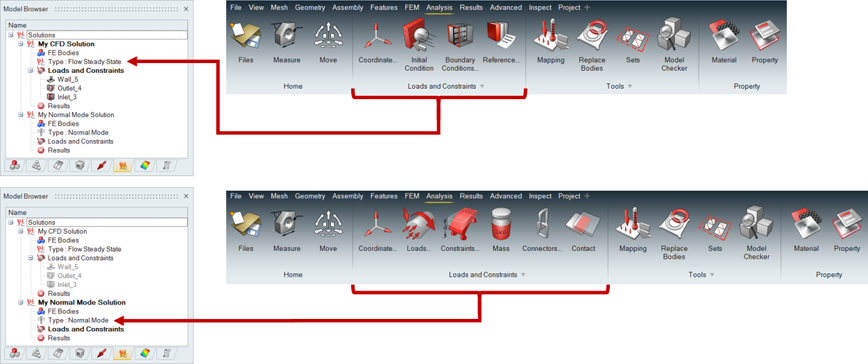
- On creating solution only valid loads and boundary conditions will be displayed
in Analysis ribbon.
- Auto contact support for Linear and Normal Mode analysis.
- The created loads and boundary conditions will be added to the current Solution / Load Case.
- Solution specific parameters can create using Solution Settings.
- The nodes and elements numbering range can be assigned in the assembly browser.
- Review Loads and Connection tool used to review the loads and connections of all the bodies in that solution.
- Boundary Condition Review Tools helps to review the specific loads such as Contact, Sets, Loadcase and so on.
- Results from a solved solution can be mapped directly to another solution as load or constraint irrespective of mesh difference. This helps in multi-physics model setup with ease. Click here for more information.
- Solution can be exported as a specification or template and can be used to transfer loads and constraints to a new mesh.
- Restart solution is used to restart the simulation from previously run.
- Duplicate solution helps to create a copy of solution with its boundary condition and settings with the same names. It helps to quickly modify parameters and re-run the analysis.
- Use Solution name > Attach Results option to attach the externally solved results to the solution.
- Response and User Defined Response can be created to fetch results of interested result components.
- Solutions Right click > Solution Folder can be specified.
- Set to Scratch Folder - This is the default SimLab scratch location for solving the solution.
- Set to Database Folder - This option will set the database location as solution solving location.
- Set to Selected Folder - Selected folder will be used for solving the solution.
- Copy Results to Database Folder Added a control whether to copy the result files in the database folder or not, while saving the database. When the Solution folder is set to scratch location then this Copy results toggle should not be turned off, otherwise, results may get deleted while closing the application.
- Import / Export Solution Template is used to export and import all the solution setups into a template file (*.slt).
- Solutions Right click > Export Responses will export responses from all the solutions. The file format can be either .xml or .slresponse. The xml file format is used in setting up DOE in HyperStudy. The .slresponse file format is used in setting up DOE in SimLab.
- Additional settings and Output requests for solution can be specified by using Solution Parameters, Result Request and Format and Spawn options.
- Solution setup can be directly used to Optimize or Compute fatigue life.
- Results will be automatically loaded on completion of solving. Also modifying
the solution parameters, material, property, and boundary condition will clear
the computed results.
- Red icon - Result is not available for the solution
- Yellow icon - Solution is solving in the background. This is supported in Windows operating system for AcuSolve, ElectroFlo, Flux, Molding, OptiStruct and Radioss solutions.
- Green icon - Result is available for the solution.
- Update(Remote Solve) feature is supported to solve the solution on remote server.
- Plot Convergence and View Log file options are supported to track and review the Solutions.
- Results Right click > Open Results Folder - This will open the folder which contains the results file while solving.
- Kill Solving feature is supported in Results right click to terminate the solving process.
- Stop after current iteration feature is supported in Results right click to stop the solving process and load the result available at that iteration.
- Export result at current time step is supported in Results right click options to generate result for the time step which is currently running. Note: This feature is supported for AcuSolve and the results will be added to the AcuSolve result file (*.log).
- Move Up and Move Down – Used to change the order of Solutions listed in solution browser.
- Scene feature is supported to capture the current model view and its display settings as scenes. Refer Scene Creation for more details.
- Generate Report feature is supported to write the report for various modules in the SimLab. For now, the scenes module is supported. Refer Generate Report for more details.
- All the Boundary conditions and connections defined in the solution will be
listed in the solution browser. If the number of load case BCs / Field table
count exceeds 100, then it will display a single compressed item [E.g.: “1200
BCs compressed”].
- “Expand All” option is available in right-click of the compressed item, this can be used to expand and display all items.
- Solution on CAD - Solution can be set up on CAD geometry to simplify model setup and utilize automated meshing capabilities.
- "Diagnose result" option can be used to display results as solver is running. This is supported for OptiStruct non-linear static / transient solutions.
- Modal Results Table
option is used to display Normal modes with their frequencies in a table format.
This option is supported for Normal mode solutions and Normal Mode
Loadcases.
Selecting a mode in the table automatically displays the corresponding eigenvector in the graphics window as a contour plot.
- Export Bodies as STL - The bodies used in the solution can be exported as multiple STL surface mesh files. Each body in the solution will be written as an STL file.