Move Tool
![]()
Introduction
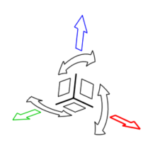
This tool is used to translate and rotate selected entities. When enabled, it will be positioned at the center of the selected entities.
It is supported for these inputs:
- Body
- Face
- Node
Body
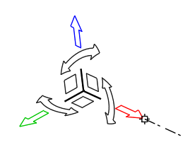
Click and drag the graphic manipulators to move entities in the selected direction or enter a value in the microdialog and press Enter on the keyboard. We can also select a manipulator to restrict translation or rotation to the selected plane or direction. Select the tool center to translate in 3D.
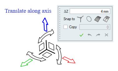
- Translate along an axis by dragging arrows.
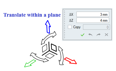
- Translate within a plane by dragging squares.
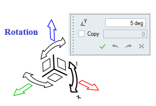
- Rotate around the center of the tool by dragging curved arrows.
- Move objects freely by dragging the center of the Move tool.
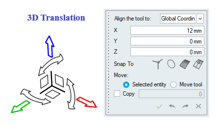
- Specify a precise magnitude to translate or rotate by clicking the graphic manipulator. Press Enter to execute the move.
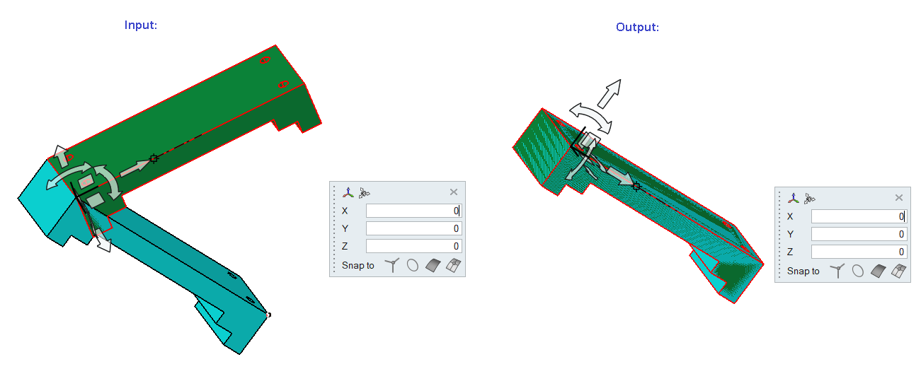
Example
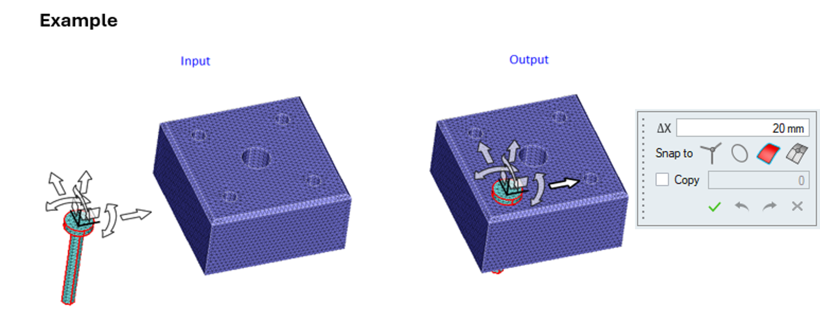
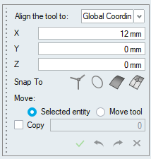
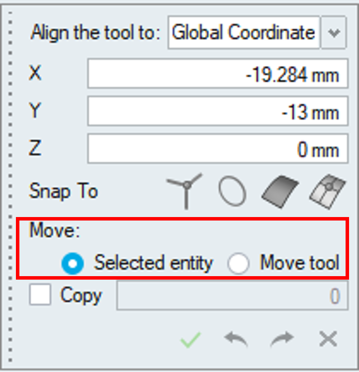
We can change the tool direction and position by using the options in the tool center micro dialog.
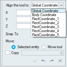
Align Tool with Global Axis
This option is used to change the tool orientation from its local axis to the global axis.
Align to Input
It is used to align the tool direction based on the selected input.
Align with Local Co-ordinate
This option is available only if local co-ordinates are defined. It lists all defined local co-ordinates, select any one of them and click the option next to it to align the tool with the selected local co-ordinate axis.
Snap
By default, snapping is supported. (i.e.) It will calculate the distance between the picked body and snap input and the body will be translated to that distance.
We can pick either node, vertex, arc edge and face as a snap input.
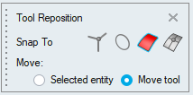
Move Options
- Selected entity
This option will move the selected bodies when the move tool marker is moved.
- Move Tool
This option will reposition the move tool alone.
Input body is differentiated with a transparent display and it is used to change the center and direction of the Move tool.
We can reposition the tool alone by picking the vertex, arc edge, face or node.
Copy Support
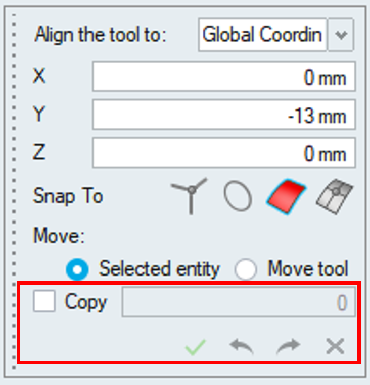
This option allows users to create body instances for the selected bodies and provides additional functionalities to manage and execute operations effectively.
Enable the toggle to activate the instance creation feature and specify the number of body instances to be created for the selected bodies.
Update [![]() ] : Operations are executed only when the Update button is
clicked. Ensure all desired changes are made before applying the update.
] : Operations are executed only when the Update button is
clicked. Ensure all desired changes are made before applying the update.
Undo [![]() ] : Enables the reversal of previous operations.
] : Enables the reversal of previous operations.
Redo [![]() ] : Allows the repetition of undone operations.
] : Allows the repetition of undone operations.
Cancel [![]() ] : Closes the dialog.
] : Closes the dialog.
Axis Alignment
This option is used to align the move tool axis to the user defined direction. Direction is defined by picking either Vertex, Node, Arc Edge or Face. It is useful in positioning the body to some other location. Pick the end points of the move tool axis to change the axis direction.
Example
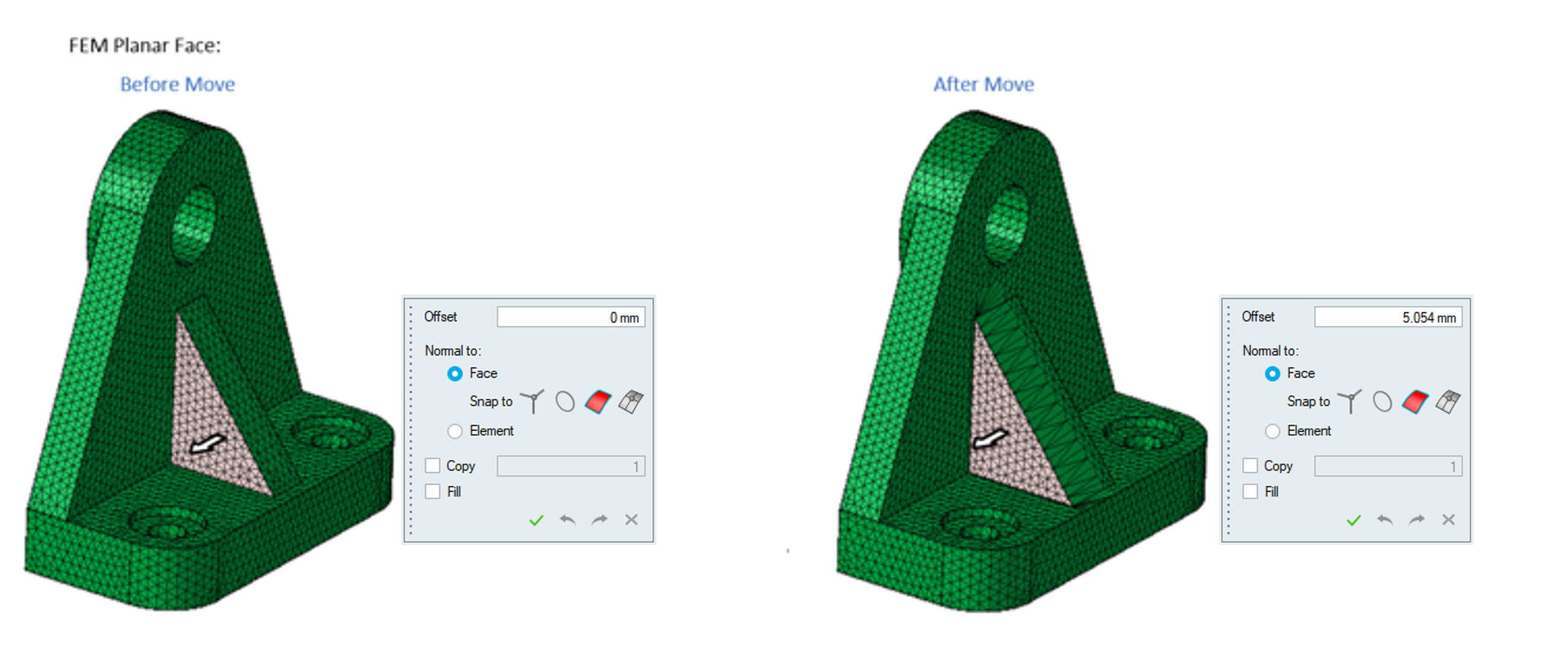
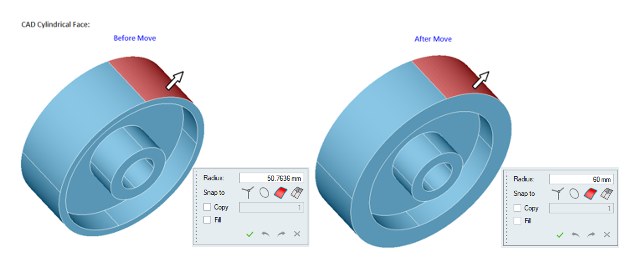
Face
- It is used to move the planar faces along normal direction and cylindrical faces along radial direction.
- Supported for FEM and Parasolid(when imported with "save geometry in database").
- Select a face and drag the marker to a specific distance and click update to perform the operation. We can also enter a value in the microdialog and press Enter.
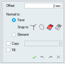
- We have added an option to move the FEM planar faces along the Face normal or its
element normal.
Example
Snap
By default, snapping is supported only when the face is moved along the face normal. (i.e.) It will calculate the distance between the picked face and snap input and the value will be updated in the Offset Edit Box. Click Update Button to perform the operation.
We can pick either node, vertex, arc edge and face as a snap input.
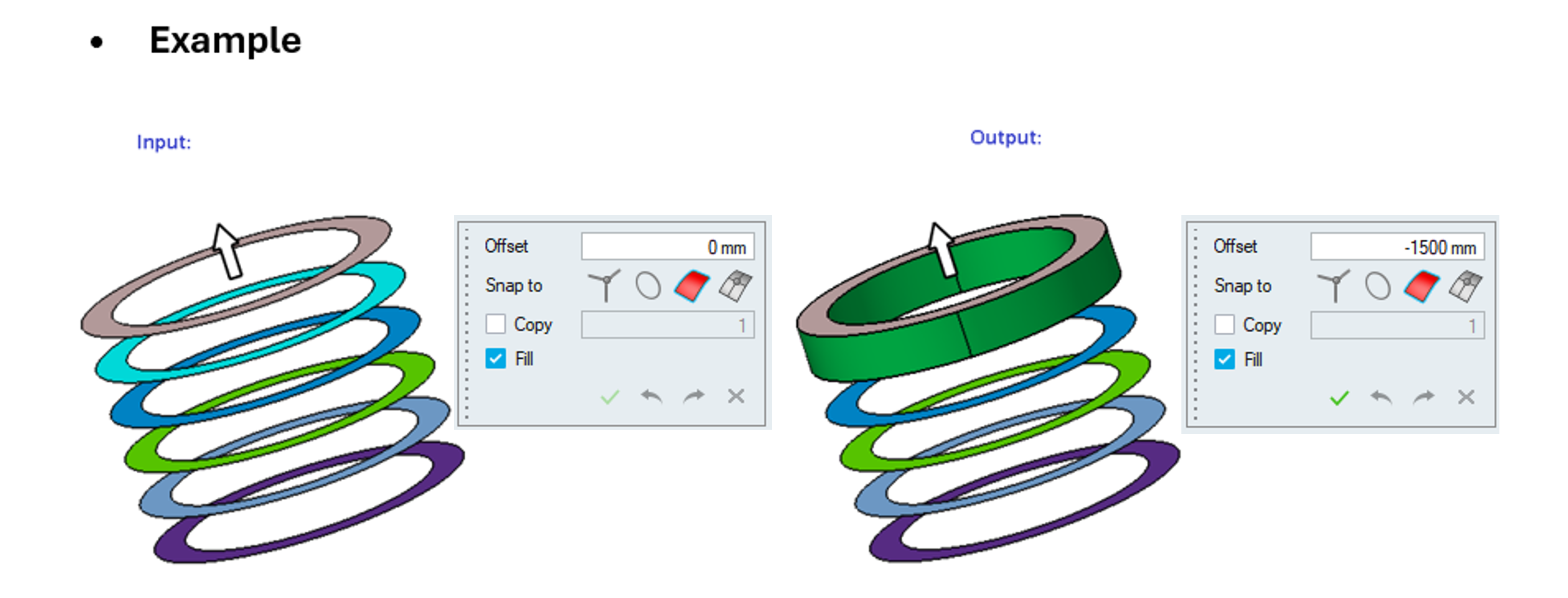
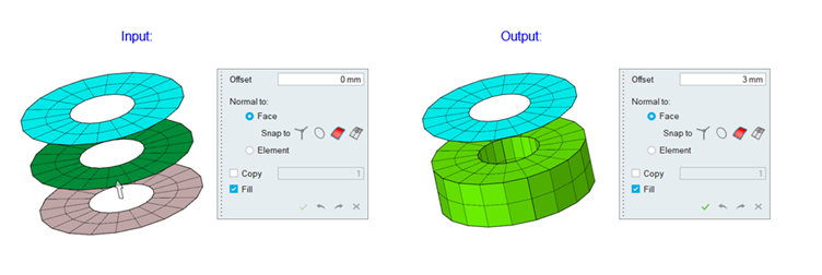
Fill
Turn on this toggle to create a new body from the input face to the offset distance. It supports both CAD and mesh inputs.
Copy
Turn on this toggle to create a copy of the selected faces.
Body / Face group input is supported for transformation.
Node
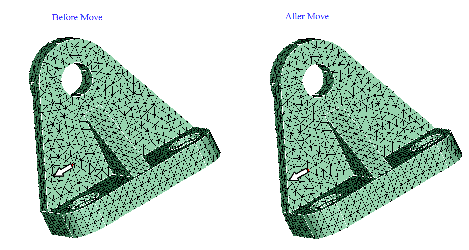
It is used to move the node along the desired direction.
Click and drag the graphic manipulators to move nodes in the selected direction or enter a distance value and press Enter on the keyboard.
We can show the tool in the specific direction by using the following options.
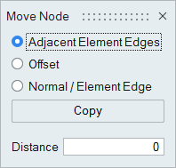
Adjacent Element Edges
It is used to move the node along the adjacent element edges. Direction will be updated when the mouse is over the element edges.
Offset
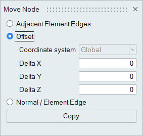
It is used to offset the node for the specified delta values along the X, Y, Z direction. By default, nodes are moved in the global co-ordinate system. We can also move along local co-ordinate by choosing in the co-ordinate system. Tool will not be visible for this option.
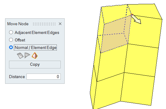
Normal / Element Edge
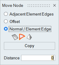
It is used to move the node using shell/solid element normal or along element edge. Direction will be updated when the mouse is over the selected entities. If nothing is picked, tool will be shown in the average normal direction.
For Solid Element, tool will be updated based on the highlighted face index.
Copy
It is used to create orphan nodes at the new position. The selected input node reset to its original position.