Selection Tool Bar
Introduction
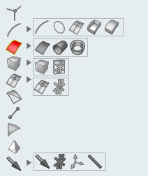
This tool bar brings up the filter menu and picking menu to pick and select which entity type should be picked.
Picking
In SimLab various picking methods are used to pick the entities. Entity picking methods are Single, Rectangle, Circle, Polygon, Intersection, Enclosed pick, visible and Pick Through Transparency.
The picking filter is shown when the “Display picking filters in GUI | Right Click” option is checked in Preference | Applications | options and vice versa.

| Single |
|
By default single entity picking mode is activate. We can active rectangle picking by using the left mouse button drag and create box to pick all closed entities. |
| Polygon |
|
Use the left mouse button and create line segments to create a polygon and close the polygon near the first point. |
| Intersection |
|
Use the left mouse button to drag and create a line segment. The line which passes through the entity will be picked. (This picking is only for element and edges.) |
| Circle | |
Use the left mouse button to drag and create a circle. All entities within the region will be selected. |
| Deselect |
|
This will deselect the selected entities, if this flag is ON, then the selected entities will be deselected corresponding to the selection filter behavior |
| Enclose |
|
This is same as rectangle, but only the fully enclosed items will be picked. |
| Visible |
|
This is also similar to rectangle picking but only the visible items will be picked. (This picking is supported for Face, Element and Nodes.) |
| Transparency |
|
This option will select the non transparent entities
through the transparent entities.(This picking is supported for Body and
Face.)
|
Selection
| Vertex |
|
This option is used to select the vertex |
| Edge |
|
This option is used to select the geometric edges. |
| Circle |
|
This option is used to select circular edges.This should be used along with edge filter. |
| Edge Path |
|
This option is used to identify the connected edges
between the start and the end edge.If the start and end edge are free edges,
then it identify the connected edges through free edge. The path can be
modified by selecting a guide edge. In this mode, when edge is selected, a
micro dialog will pop up with three options. Reject: This will clear all the identified edges. Confirm: This will add the identified edges to the selection list. Cancel: This option will clear the selection list and filter will be set to Edge mode. |
| Free Edge Loop |
|
This option is used to select loop of free edges. This should be used along with edge filter. |
| Edge Loop |
|
This option is used to select loop of edges. This should be used along with edge filter. |
| Face |
|
This option is used to select the face. |
| Cylinder/Cone |
|
This option is used to select cylindrical/conical faces. |
| Fillet |
|
This option is used to select connected fillets. Fillet loop can be used on CAD/FEM surfaces.This should be used along with face filter. |
| Face by Angle | This option is used to select all the adjacent faces whose included angle falls below the given angle. | |
| Body |
|
This option is used to select the surface, RBE and Bar body. |
| RBE Body |
|
This option is used to select only RBE body. |
| Node |
|
This option is used to select the nodes. |
| RBE Node |
|
This option is used to select RBE nodes. |
| Node Path | As we pick a node, all the intermediate nodes between the previous and current nodes get identified and added to the selection. The node path is decided based on the feature angle between the previous and current node selection. | |
| Element Edge |
|
This option is used to select the element edges. |
| Bar Element |
|
This option is used to select bar elements. |
| Element |
|
This option is used to select the shell elements. |
| Solid Element |
|
This option is used to select the solid elements. |
| Loads |
|
This option is used to select the loads. |
| RBE |
|
This option is used to select RBE elements. |
| Co-ordinate |
|
This option is used to select co-ordinate system. |
| RBAR |
|
This option is used to select RBAR body. |
| Region Object |
|
This option is used to select Virtual Region Objects (Box, Cylinder, Cone etc...). |
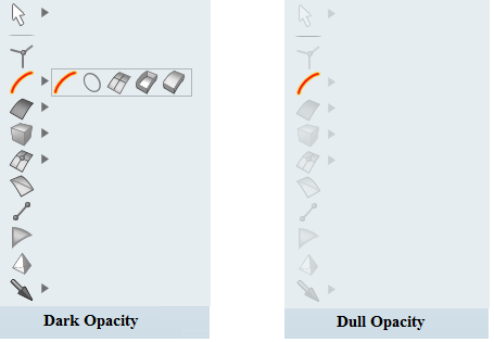
when mouse over the selection tool, it is display with dark opacity. Otherwise it is display with dull opacity.
By clicking these filters, only the desired entities will be highlighted and selected. Simlab tries to activate these filters automatically depending on the context of the operations and functions/Dialog boxes used at a particular time.