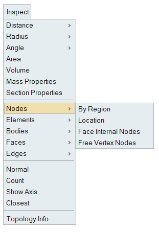
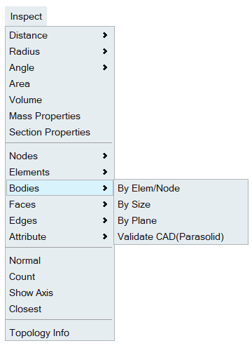
Inspect
Introduction
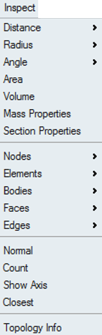
Inspect tool is used to measure or identity the following:
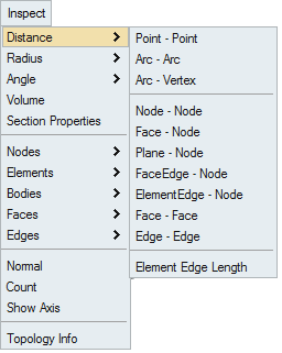
Distance
This option is used to measure the distance between the selected entities.
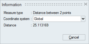
This tool opens Information dialog box. We can repeat the measurement multiple times using this dialog. Once the measurements are done close the dialog box either by clicking "Cancel" button or "Esc" key.
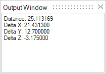
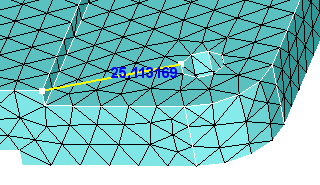
The measured value is displayed in the Information dialog box and also in the SimLab output window.
Point - Point Options
Distance between two points. Pick first point on a vertex by clicking the left mouse button and move the mouse to a desired distance. The distance moved will be displayed on the screen. Picking second point on the vertex will show the distance between the two points in the dialog and in the output window.
Others Options
Rest of the measurement options in the menu are entity based.
| Option | Description |
|---|---|
| Arc - Arc | Distance between two Arc (Edge) centers. |
| Arc - Vertex | Distance between Arc (Edge) center and an vertex. |
| Node - Node | Distance between two nodes. |
| Face - Node | Shortest distance between a face and a node. |
| Plane - Node | Distance between a plane and a node. Select an element to define the plane. |
| FaceEdge- Node | Shortest distance between a topological edge and a node. |
| ElementEdge - Node | Shortest distance between an element edge and a node. |
| Face - Face | Shortest distance between two faces. Supported for both CAD and FEM. |
| Edge - Edge | Shortest distance between two edges. Supported for both CAD and FEM. |
| Element Edge Length | Gives the length of an element edge. |
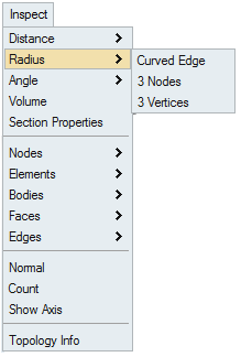
Radius
This option is used to measure the radius of an arc edge or the arc formed by the selected three nodes or the arc formed by the selected three vertices.
Angle
This option is used to measure the angle between entities.
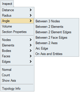
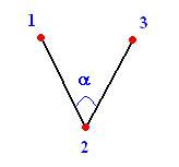
- Between 3 Nodes: To find the angle between the lines formed by three
nodes. Numbers (1, 2, and 3) shown in the picture represents the node selection
order.
-
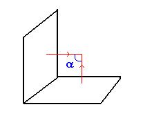
Between 2 elements: To find the angle between two elements. It gives the angle between the element normals.
-
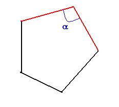
Between 2 element edges / face edges: To find the angle formed by the two element edges or the topological edges.
-
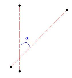
Between 2 axes: To find the angle formed by the axis of the two arc edges.
-
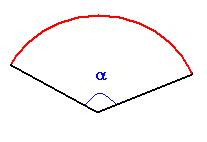
Arc Edge
To find the arc segment angle.
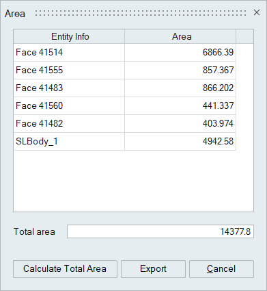
Area
This option calculates the area of the selected faces and bodies.
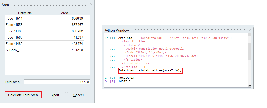
Click “Calculate Total Area” to compute the cumulative area of the selected entities.
Users can export this information to a CSV file.
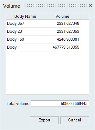
Volume
This option is used to calculate the volume for the selected bodies.
Body name and corresponding volume will be displayed in tabular form. Cumulative volume of the selected bodies will also be displayed.
User can export these information to a CSV file.
Mass Properties
This option is used to compute the mass properties of CAD and mesh bodies and point masses.
Computation of mass properties is supported for the following,
- Solid Body
- Shell Body
- Bar Body
Prerequisites for mass properties
Needs density parameter for computing mass properties. So, material property needs to be defined for the bodies.
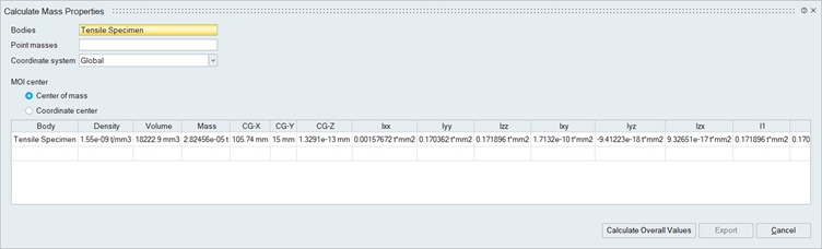
Output of mass properties
The following mass and inertia parameters are computed and displayed in the dialog,
- Volume
- Mass
- Center of Mass - CG-X,CG-Y,CG-Z
- Mass Moments of Inertia about center of mass or about the coordinate center(Ixx,Iyy,Izz,Ixy,Iyz,Izx)
- Principal Moments of Inertia about center of mass or about the coordinate center(I1,I2,I3)
Overall Mass Properties
To compute overall mass properties of the selected bodies, Click "Calculate Overall Values". The overall mass properties information will be displayed in the last row of the table.
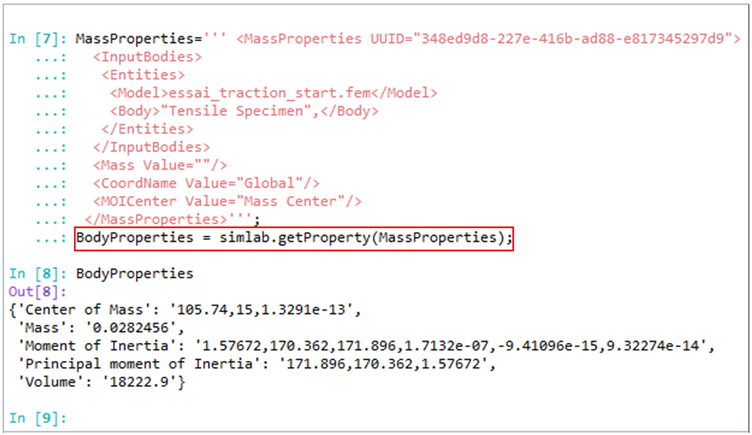
Export Mass Properties
The Mass properties information can be exported as .csv format. Also, scripting is supported for export which helps in automation.
- Only Bar bodies with circular cross section is supported for mass properties calculation.
- For other cross sections, Volume and Mass will be calculated but Inertia parameters will be displayed as zero.
- The script command for the Overall Mass Properties returns the body properties values in dictionary format. Users can manipulate the returned values.
- In the script, set the MOICenter parameter to either “Mass Center” or “Coordinate Center” to calculate the moment of inertia relative to the center of mass or the coordinate center.
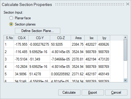
Section Properties
This option is used to compute the section properties - Centroid, Area and Moment of Inertia.
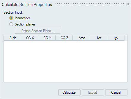
Section properties can be computed for:
- Planar face - CAD/Mesh
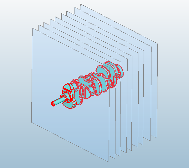
- Section plane cuts defined on a body CAD bodies / Mesh bodies
- Local Coordinate System Support: The tool now supports calculations in a user-defined Local Coordinate System (LCS) using rectangular coordinates.
- Multiple Body Input: Users can select multiple bodies when creating a section plane, enabling more dynamic section property calculations.
- Summation of Inertia for Multiple Bodies:
- When a section plane intersects multiple bodies, the tool calculates the section properties for all faces generated by the intersection.
- The output displays the combined inertia values, representing the total inertia for all intersected bodies within the section plane.
The calculated section properties are displayed in a tabular form as shown below and it can be exported as CSV format file.
Export option is scriptable.
Known Limitation: For CAD models, section properties calculation works only for parasolid and step formats.
Nodes
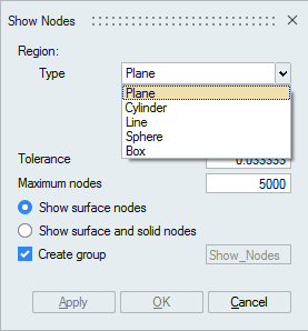
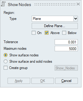
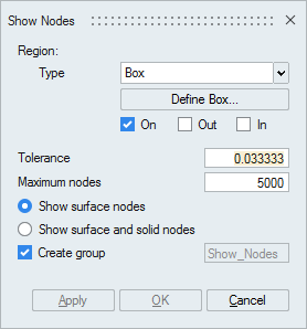
- By Region
This option works for the selected FEM bodies or faces. The nodes will be displayed based on the defined region (Plane/Cylinder/Line/Sphere/Box).
Checking the Show surface and solid nodes option displays internal nodes in the selected solid body.
If the nodes found exceeds the number of nodes entered in Maximum nodes field, then the nodes upto the maximum count will only be displayed. Remaining nodes will not be displayed.
Checking the Create group creates a group containing the displayed nodes
-
Plane
Plane can be defined using the Define/Modify Plane option.
On option displays the nodes that are lying on the defined plane. Distance between the node and the defined plane should be less than or equal to the given Tolerance.
Above option displays the nodes that are lying above the plane. Distance between the plane and the node in the plane direction should be greater than the given Tolerance.
Below option displays the nodes that are lying below the plane. Distance between the plane and the node in the opposite direction of the defined plane should be greater than the given Tolerance
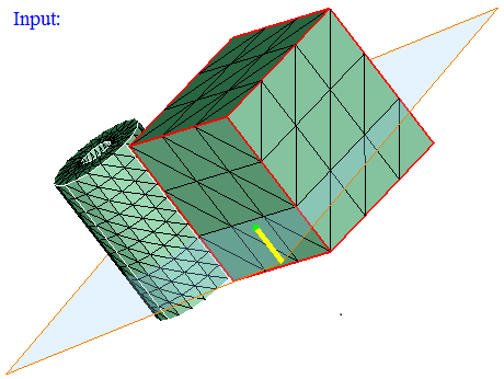
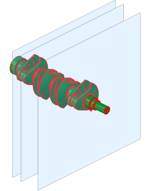
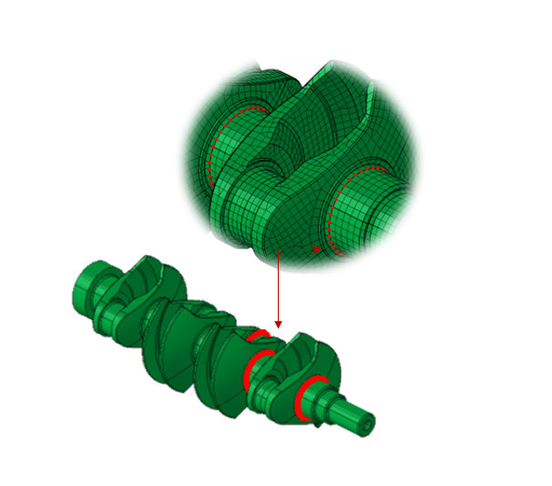
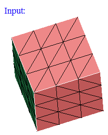
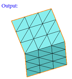
Using Multiple Planes:
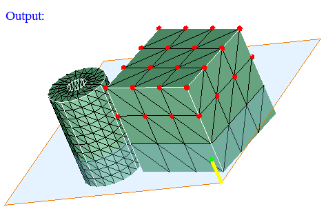
Input:
Output:
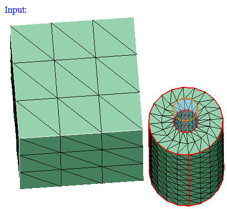
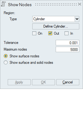
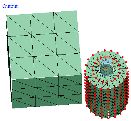
- Cylinder
Cylinder can be defined using the Define/Modify Cylinder option.
On option displays the nodes that are lying on the defined cylinder. Let 'r' be the radius of the defined cylinder and 'd' be the distance between the node and the axis, then (r+ Tol) >= d >= (r- Tol).
Out option displays the nodes that are lying outside (d > r + Tol) the cylinder.
In option displays the nodes that are lying inside the cylinder (d < r - Tol).
-
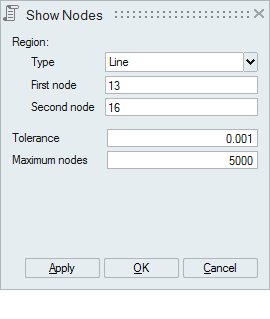
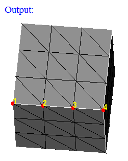
Line
Line can be defined by selecting any 2 nodes. Set the focus on the "First Node" and select a node. And set the focus on the second node and select the another node defining the line.
Distance between the displayed nodes and the line should be less than or equal to the "Tolerance".
-
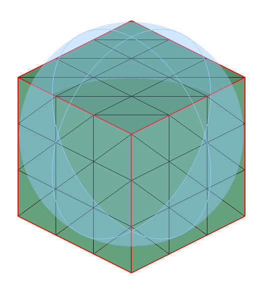
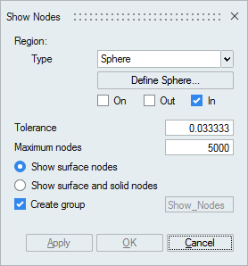
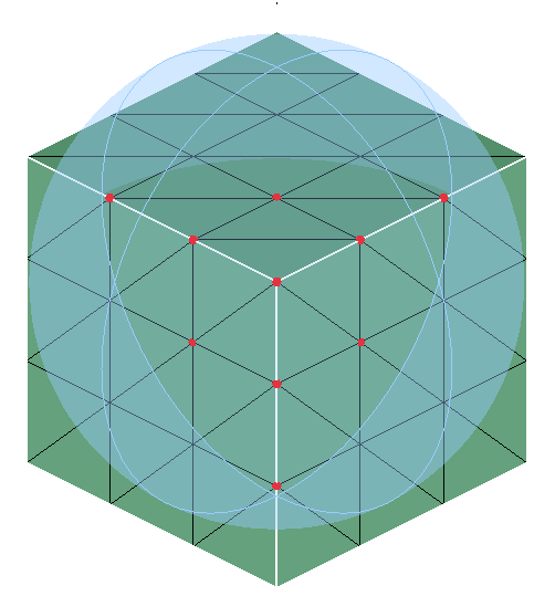
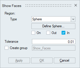
Sphere
Sphere can be defined using the Define/Modify Sphere option.
On option displays the nodes that are lying on the defined Sphere. Let 'r' be the radius of the defined Sphere and 'd' be the distance between the node and the center, then (r+ Tol) >= d >= (r- Tol).
Out option displays the nodes that are lying outside (d > r + Tol) the Sphere.
In option displays the nodes that are lying inside the Sphere (d < r - Tol).
-
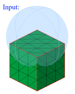
Input:
-
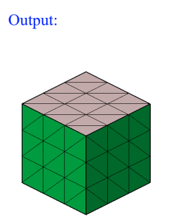
Output:
-
-
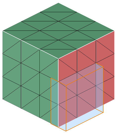
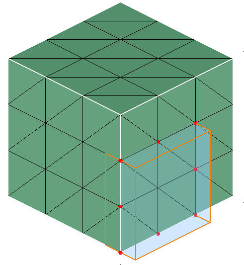
Box
Box can be defined using the Define/Modify Box option.
On option displays the nodes that are lying on the defined Box. Distance between any one of the planes of the box and node should be less than or equal to the given Tolerance.
Out option displays the nodes that are lying outside the Box. Distance between planes of the box and node in the plane direction should be greater than the given Tolerance.
In option displays the nodes that are lying inside the Box. Distance between planes of the box and node in the opposite direction of plane should be greater than the given Tolerance.
-
Input:
-
Output:
-
-
- Location
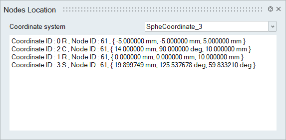
This option displays the selected node location for the selected Coordinate system.
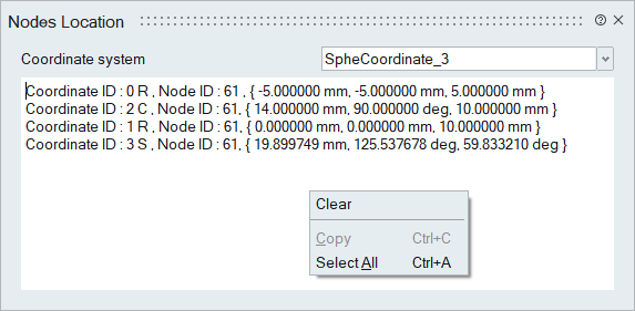
Co-ordinates shown in the LBC tab in Model Browser will be displayed in the "Coordinate system" combo box. Select a coordinate system and then select a node. Corresponding node location will be printed in this dialog and in the output window. If more than one node is selected, the information for the last selected node will always be displayed. When nodes are selected consecutively, their corresponding locations will be appended to the dialog. To clear the output window, use the "Clear" option from the right-click context menu. This action will also unselect the nodes in the selection list.
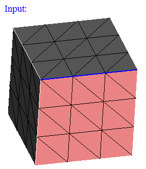
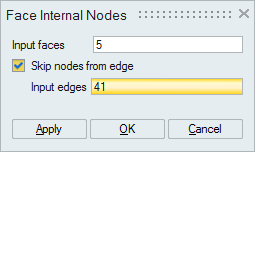
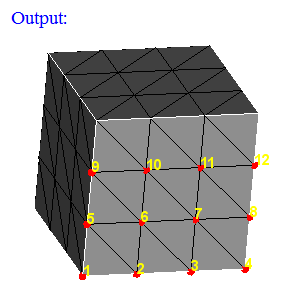
- Face Internal Nodes
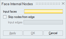
This option displays the nodes (Corner nodes and Mid nodes) in the selected faces. By default, it will not display the nodes in its topological edges.
If you do not want to ignore the nodes of all the topological edges, then by checking the "Skip nodes from edge" option and selecting the topological edges will ignore only the nodes of the selected edges. So that the nodes in the remaining topological edges will be displayed.
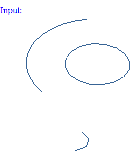
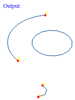
- Free Vertex Nodes
This option displays the nodes in the free vertices of the selected wire body.
Elements
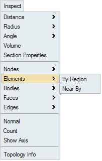
- By Region
This option works for the selected FEM bodies or faces. The elements will be displayed based on the defined region (Plane/Cylinder/Line/Sphere/Box).
If the elements found exceeds the number of elements entered in "Maximum elements" field, then the elements upto the maximum count will only be displayed. Remaining elements will not be displayed.
Checking the Create group creates a group containing the displayed elements.
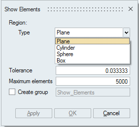
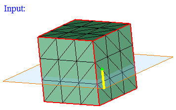
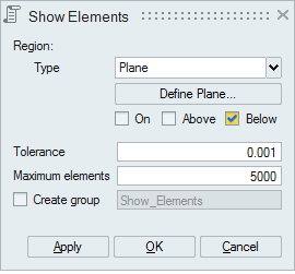
Plane
Plane can be defined using the Define/Modify Plane option.
If all the corner nodes of an element are on the defined plane then that element will be displayed using On option. Distance between the node and the defined plane should be less than or equal to the given Tolerance.
If all the corner nodes of an element are above the defined plane then that element will be displayed using Above option. Distance between the plane and the node in the plane direction should be greater than the given Tolerance.
If all the corner nodes of an element are below the defined plane then that element will be displayed using Below option. Distance between the plane and the node in the opposite direction of the defined plane should be greater than the given Tolerance.
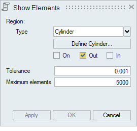
- Cylinder
Cylinder can be defined using the Define/Modify Cylinder option.
If all the corner nodes of an element are on the surface of defined cylinder then that element will be displayed using On option. Let 'r' be the radius of the defined cylinder and 'd' be the distance between the node and the axis, then (r+ Tol) >= d >= (r- Tol).
If all the corner nodes of an element are lying outside of the defined cylinder and (d > r + Tol) then that element will be displayed using Out option.
If all the corner nodes of an element are lying inside of the defined cylinder and (d < r - Tol) then that element will be displayed using In option.
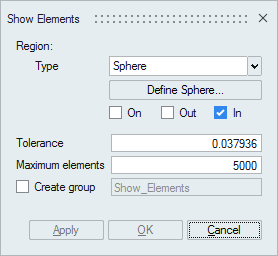
- Sphere
Sphere can be defined using the Define/Modify Sphere option.
If all the corner nodes of an element are on the surface of defined sphere then that element will be displayed using On option. Let 'r' be the radius of the defined sphere and 'd' be the distance between the node and the center, then (r+ Tol) >= d >= (r- Tol).
If all the corner nodes of an element are lying outside of the defined sphere and (d > r + Tol) then that element will be displayed using Out option.
If all the corner nodes of an element are lying inside of the defined sphere and (d < r - Tol) then that element will be displayed using In option.
-
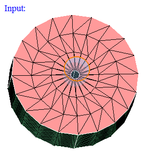
Input:
-
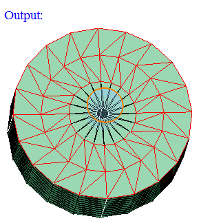
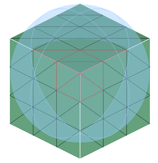
Output:
-
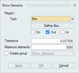
- Box
Box can be defined using the Define/Modify Box option.
If all the corner nodes of an element are on the surface of defined Box then that element will be displayed using On option. Let d be the distance between any one of the planes of the box and a node, then d <= Tol.
If all the corner nodes of an element are lying inside the Box and (d > Tol) then that element will be displayed using In option.
If all the corner nodes of an element are lying outside the Box and (d > Tol) then that element will be displayed using Out option.
-
Input:
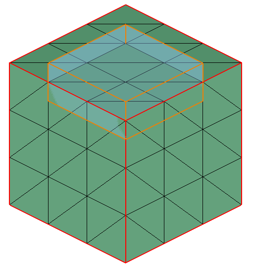
- Output:
-
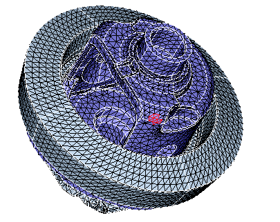
- Near By
This option displays the near by elements of the given input elements.
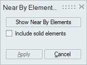
Include solid elements
Enabling this option will display the near by solid elements in addition to the surface elements.
Steps
- Select input elements and click on Show NearBy Elements. This will display the elements around the given input elements.
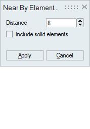
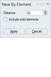
- Distance will be shown after displaying near by elements. Now the user can increase or decrease the distance of elements shown, also the user can specify any desired distance.
Example
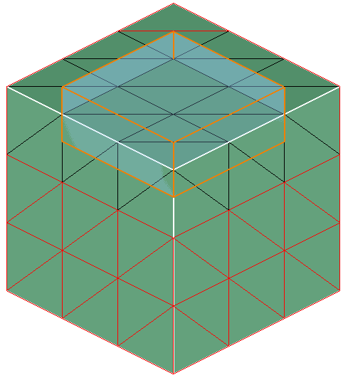
The input elements are shown below.
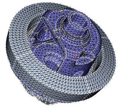
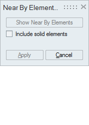
After clicking Show Near By Elements, the following output will be obtained. Now the user can increase or decrease the distance or can specify any desired distance.
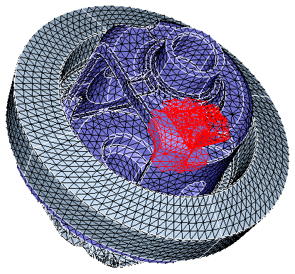
The following output shows near by elements of distance 30 around the input elements.
Bodies
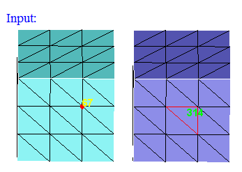
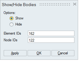
- By Elem/Node
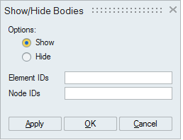
This option works for the selected shell elements and nodes. Set the focus on the "Element IDs" edit box, and select the shell elements. This will display the element's ID. Same way, set the focus on the "Node IDs" edit box and select nodes.
"Show" option will add the bodies which are having the selected elements and nodes to the selection list, it will show that bodies only in UI and all the other bodies are invisible . If "Hide" option is selected, then those bodies will be hidden.
- By Size
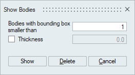
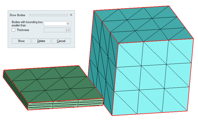
This option is used to identify small bodies. Bodies whose bounding box size is smaller than the user given size will be displayed. Thickness option is used to identify thin bodies less than the specified value.
Show: This option show the bodies that are smaller than the user given bounding box size.
Delete: This option is used to delete the bodies that are smaller than the user given bounding box size.
- Example 1 (Thickness = OFF)
-
Example2 (Thickness = ON)
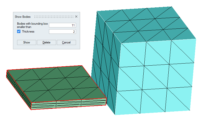
Note: Scripting is supported for Delete option only. - Example 1 (Thickness = OFF)
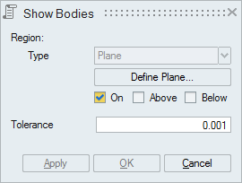
- By Plane
This option is used to identify the bodies that lie above or below or on the plane.
- Validate CAD Parasolid
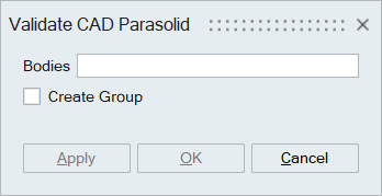
Parasolid bodies can sometimes be invalid and may fail in CAD operations. This option helps to identify the invalid bodies and faces, as well as the edges of faces that failed to display, possibly due to invalid geometry details. It creates failure groups named “Invalid_Bodies,” “Invalid_Faces,” and “DisplayErrorFaceBoundaries” respectively.
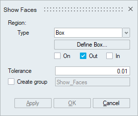
Faces
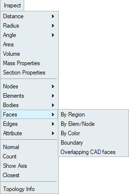
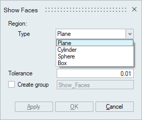
- By Region
This option works for the selected FEM/CAD bodies or faces. The faces will be displayed based on the defined region (Plane/Cylinder/Sphere/Box).
Checking the Create group creates a group containing the displayed faces.
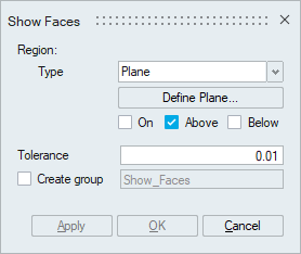
- Plane
Plane can be defined using the Define/Modify Plane option.
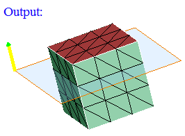
"On" option displays the faces that are lying on the defined plane. Distance (d) between the nodes of the face and the defined plane should be less than or equal to the given "Tolerance".
"Above" option displays the faces that are lying above the plane (d > Tol).
"Below" option displays the faces that are lying below the plane (d > Tol).

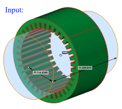
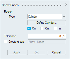
- Cylinder
Cylinder can be defined using the Define/Modify Cylinder option.
If all the nodes of a face and centroid of all the elements of a face are on the surface of a defined cylinder, then that face will be displayed using the On option. Let 'r' be the radius of the defined cylinder and 'd' be the distance between the node and the axis, then (r + Tol) >= d >= (r - Tol).
If all the nodes of a face and centroid of all the elements of a face are lying outside of the defined cylinder and (d > r + Tol), then that face will be displayed using the Out option.
If all the nodes of a face and centroid of all the elements of a face are lying inside of the defined cylinder and (d < r - Tol), then that face will be displayed using the In option.
- Sphere
Sphere can be defined using the Define/Modify Sphere option.
If all the nodes of a face and centroid of all the elements of a face are on the surface of a defined sphere, then that face will be displayed using the On option. Let 'r' be the radius of the defined sphere and 'd' be the distance between the node and the center, then (r + Tol) >= d >= (r - Tol).
If all the nodes of a face and centroid of all the elements of a face are lying outside of the defined sphere and (d > r + Tol), then that face will be displayed using the Out option.
If all the nodes of a face and centroid of all the elements of a face are lying inside of the defined sphere and (d < r - Tol), then that face will be displayed using the In option.
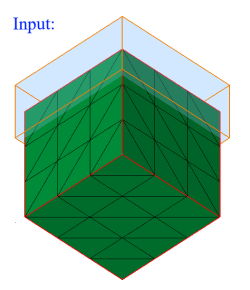
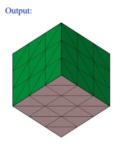
- Box
Box can be defined using the Define/Modify Box option.
If all the nodes of a face and centroid of all the elements of a face are on the surface of a defined box, then that face will be displayed using the On option. Let d be the distance between any one of the planes of the box and a node, then d <= Tol.
If all the nodes of a face and centroid of all the elements of a face are lying outside of the defined box and (d > Tol), then that face will be displayed using the Out option.
If all the nodes of a face and centroid of all the elements of a face are lying inside of the defined box and (d > Tol), then that face will be displayed using the In option.
- Plane
-
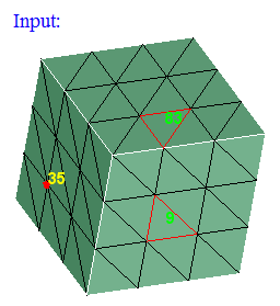
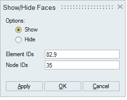
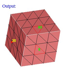
By Elem / Node
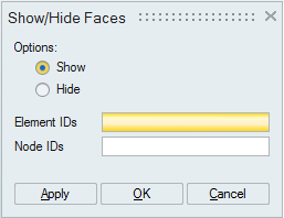
This option works for the selected shell elements and nodes. Set the focus on the "Element ID" edit box, and select the shell elements. This will display the element's ID. Same way, set the focus on the "Node ID" edit box and select nodes.
"Show" option will add the faces which are having the selected elements and nodes to the selection list. If "Hide" option is selected, then those faces will be hidden.
This is mainly used to show the faces when we do free edge display using Mesh|Verify|Edges.
-
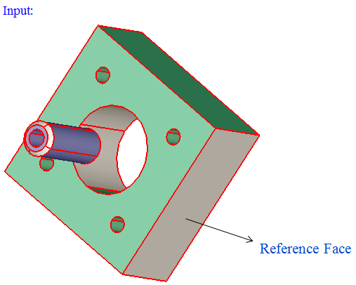
By Color
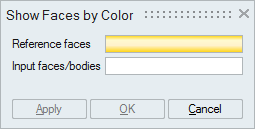
This option works for the selected faces or bodies (for both FEM and CAD).
To set the color for the faces, select the faces and right click on the client area. This will popup a menu. There is an option named "Color". This will help to set the color for the selected faces.
To set the color for the faces, select the faces and right click on the client area. This will popup a menu. There is an option named "Color". This will help to set the color for the selected faces.
Also color of faces which are assigned in Catia part can be imported into SimLab by checking the option "Color".
To view the color of the faces, enable "Render Mode -> Face Color" option.
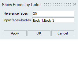
Set the focus on the "Reference faces" option and select the faces.
Set the focus on the "Input faces/bodies" option and select either faces or bodies.
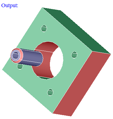
From the input bodies or faces, those faces having the color same as the color of the "Reference faces" will be displayed.
-
Boundary
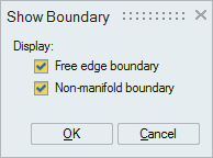
This option works for the selected FEM faces.
"Free edge boundary" option displays free element edges in the selected faces by considering their boundary as free edges even they are having adjacent faces.
"Non-manifold boundary" option displays non-manifold element edges in the selected faces.
To know the definition for free edge and non-manifold edge, see Mesh|Verify|Edges.
-
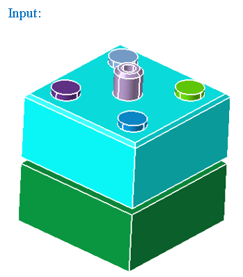
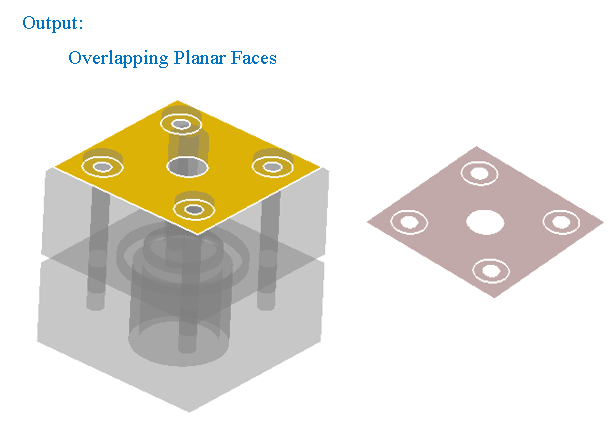
Overlapping CAD Faces
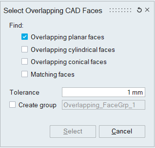
This option works for the selected CAD bodies. Atleast two bodies should be selected.
-
"Overlapping planar faces" option displays the planar faces that are overlapping between the selected bodies.
-
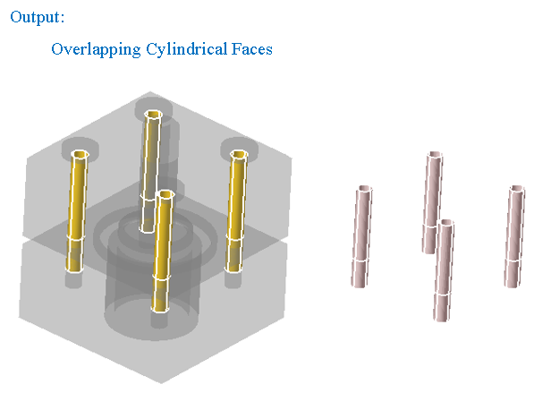
"Overlapping cylindrical faces" option displays the cylindrical faces that are overlapping between the selected bodies.
Distance between the displayed overlapping faces should be less than the given "Tolerance"
-
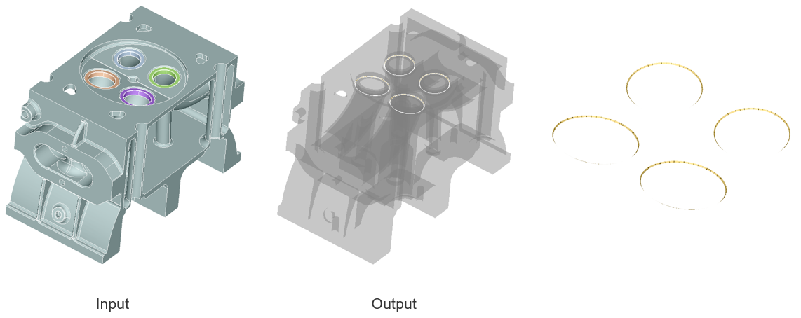
"Overlapping conical faces" option displays the overlapping conical faces in the selected bodies.
-
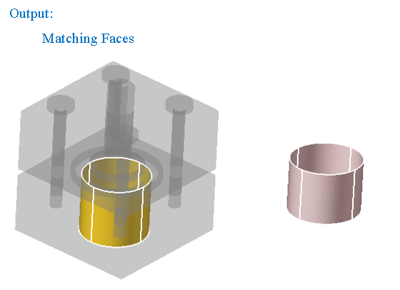
"Matching faces" option displays the faces of any shape which are exactly matching and overlapping between the selected bodies.
-
" Select " option is used to display the overlapping CAD faces between bodies. The overlapping CAD faces can be automatically stored in a face group. This is a temporary group and it will be deleted during Redisplay or Reset.
-
"Create group" option is used to add overlapping CAD faces in a group. It creates group with user specified name. Before creating a group, it will do duplicate check. If the faces are already present in any of the group, it will post a warning message to overwrite in the same group or not.
-
Edges
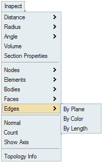
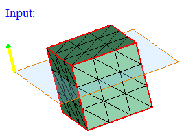
- By Plane
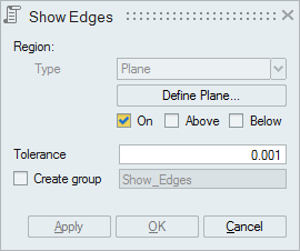
This option works for the selected FEM/CAD bodies or faces.
Plane can be defined using the Define/Modify Plane option.
"On" option displays the edges that are lying on the defined plane. Distance (d) between the nodes of the edges and the defined plane should be less than or equal to the given "Tolerance".
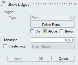
"Above" option displays the edges that are lying above the plane (d > Tol).
"Below" option displays the edges that are lying below the plane (d > Tol).
-
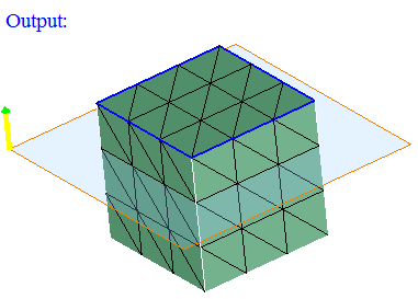
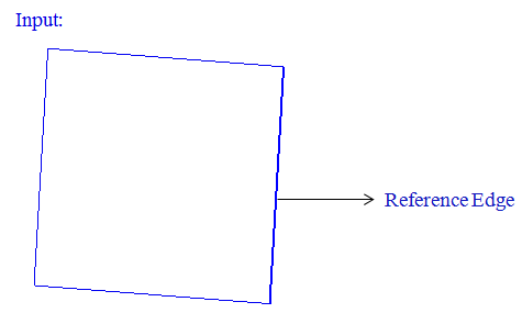
By Color

This option works for the selected edges or bodies (for both FEM and CAD).
To view the color of the edges, enable "Render Mode -> Edge Color" option.
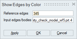
Set the focus on the "Reference edges" option and select the edges.
Set the focus on the "Input edges/bodies" option and select either edges or bodies.
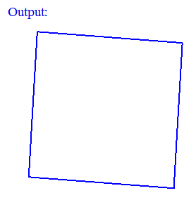
From the input bodies or edges, those edges having the color same as the color of the "Reference edges" will be displayed.
- By Length
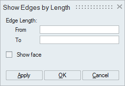
Select one or more bodies or faces and specify the edge length range. The edges of the selected body or face within the specified range will be displayed.
If the "Show face" option is enabled, then the faces of those edges will be displayed
Normal
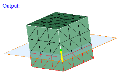
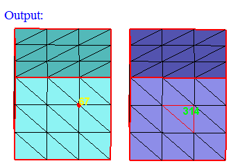
This option allows you to visualize and reverse the element normal.
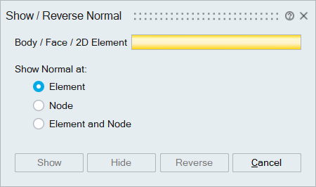
Body / Face / 2D Element
Select bodies or faces or 2D elements as input.
Show Normal at
Users can select any options below to display the normal at the node, element, or both node and element.
- Element
Select this toggle to display the normal of each 2D element in the selected entity.
- Node
Select this toggle to display the average normal of 2D elements connected to each node.
- Element and Node
Select this toggle to display the average element normal calculated for each node and the normal for each 2D element.
Show
To display the normal of the selected entities.
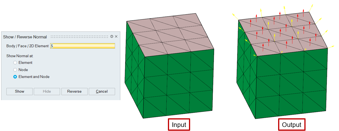
In this example, the "Red" arrows represent the element's normal, and the "Yellow" arrow represents the average element normal calculated for each node.
Hide
To hide the normal in the display.
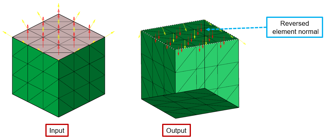
Reverse
To reverse the element's normal for all the 2D elements in the selected entity.
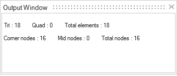
Count
This option is used to find the number of nodes and elements on the selected faces or edges. Node and Element count will be printed on the output window.
Show Axis
This option is used to visually see the axis of the cylindrical faces or arc edges.
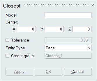
Closest
This option is used to identify the closest entity (body, face, edge, vertex, node, element) in a model from the node/vertex/xyz position. Output entity will be added in a group. When tolerance is given, those entities that are within the tolerance will be added.
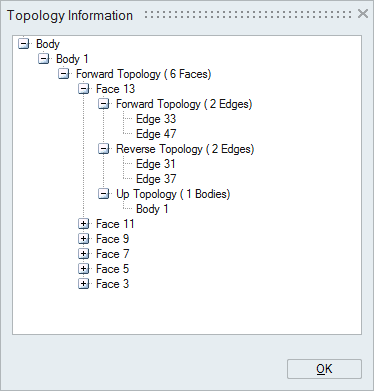
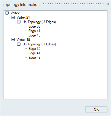
Topology Info
This option helps to know the way on how the entities (body / face / edge / vertex) are connected together to form a model.
Topology information will be displayed in terms of "Forward Topology", "Reverse Topology", and "Up Topology".
"Forward and Reverse Topology" of a selected entity displays the entities which bounds the selected entity.
"Up Topology" of a selected entity displays the entities bounded / formed by the selected entity.
Vertices (points) are used to define line (an Edge). So the edges formed by the selected vertex will be displayed in its up topology. And this will not have any forward/reverse topology.
Since vertices forms an edge, that will be displayed as forward and reverse topology of the selected edge. Forward and reverse vertices will be found from the arrangement of bar elements in an edge. A circular edge will have only one vertices and this will be either added to forward or reverse topology.
Boundary of a face is determined from its topological edges. So an edge will have faces in its up topology.
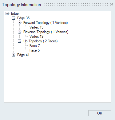
Since face is bounded by edges, edges will be displayed in its forward and reverse topology. Forward and reverse topology is determined from the bar element and shell element orientation. If the nodes in the bar and shell element are in same direction, then those edges will be added to forward topology. If not so, then it will be added to reverse topology.
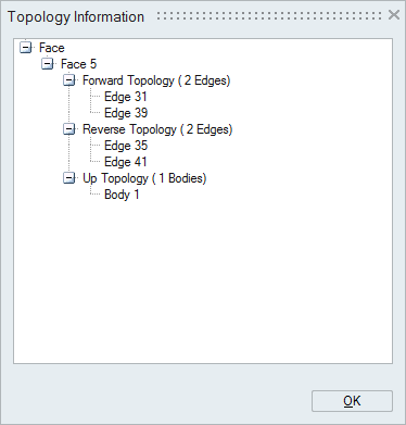
Since body is bounded by faces, face will have body in its up topology. If it is having 2 bodies in its up topology, then that face is known as a shared face between the bodies. And body will have faces in its forward and reverse topology. And this will not have any up topology.