Define Plane
Dialog Box
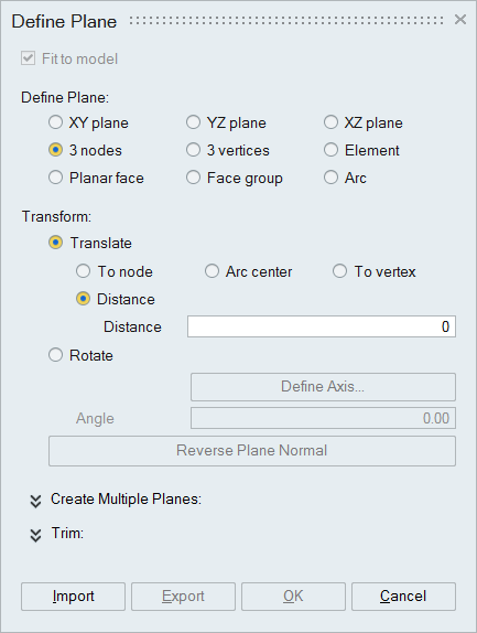
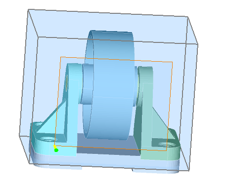
This option is used to define a plane.
Fit to model
This option is enabled only in Break Body (Plane) dialog. Turn off this toggle will define the finite plane.Define Plane
XY, YZ, XZ plane: Defines a plane on the corresponding plane of the selected coordinate system, positioned at the center of the model.
- The Coordinate system option is available only for XY, YZ, and XZ plane and requires at least one local coordinate system in the current database.
3 nodes: Pick three non-collinear nodes to define a plane.
3 vertices: Pick three non-collinear vertices to define a plane.
Element: Pick an element to define a plane.
Planar face or Face group: Pick planar face to define a plane.
Arc: Pick an arc to define a plane. From this arc three points will be calculated for defining the plane.
Transform
- Translate: Used to move plane at the desired position.
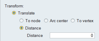
- To node: Pick a node to move the plane to that point.
- Arc center: Pick an arc to offset the plane. The plane will be moved to the center of the arc.
- To vertex: Pick a vertex to move the plane to that point.
- Distance: Enter the value or place the cursor inside the Distance box and scroll the mouse. The plane will be moved to this distance.
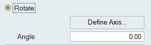
- Rotate: Used to rotate the plane based on the axis and angle
defined.
-
Define Axis: If any of the planes is active, then the “Define Axis...” button will be enabled. Click to define the rotation axis.
-
Angle: After defining the rotation axis, the Angle edit box will enabled. Enter the angle or place the cursor inside the box and scroll the mouse to rotate the plane.
-
Reverse Plane Normal
To reverse the direction of the plane normal.
- Create Multiple Planes
User can create multiple planes by two methods namely,
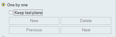
- One by One
-
New: Create the plane and click this button to insert the plane in to the list. Then create second plane and click new to include that plane to the list. Thus any number of planes can be created successively.
- Previous/Next: This button is used to activate the previously created planes. The active plane will be highlighted. And also used to travels the multiple cylinders list.
- Delete: Used to delete the highlighted plane.
-
- Array
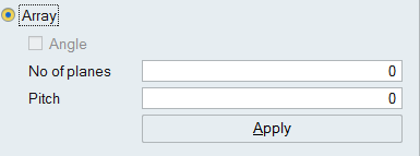
Create the reference plane and enter the No of planes and Pitch value. Click “Apply” to create the array of plans from reference plane. The arrow mark in yellow color shows the normal of the plane. The array of planes will be created in this direction. Use “Reverse Plane Normal” option to change the normal of the plane.
- One by One
- Trim
This option is used to define planes, which not necessarily pass through the entire body. Some times a plane may be required to pass only to some extent on the body and this option just enables the user to do that. The body will be broken in the limited region bounded by these planes.
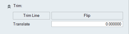
- Trim Line: After defining a plane, click this button to define the bounded axis. When this axis is defined, only the body starting from this axis will be broken. The body portion lying behind this axis will remain unaffected. The yellow line highlighted in plane is the Trim Line.
- Flip: Click to change the direction of the bounded plane.
- Translate: Enter the value or place the cursor inside the box and scroll the mouse to translate the bounded plane.
Export
The created planes can be exported and saved in the .xml format.
Import
This is used to import the plane data saved in .xml format.
Special Case
Box Face:
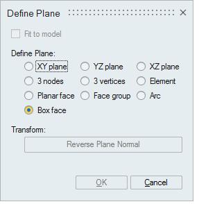
This option is shown only in nFx → Inlet dialog. It is used to define a plane by picking the box face.