Define Box
Dialog Box
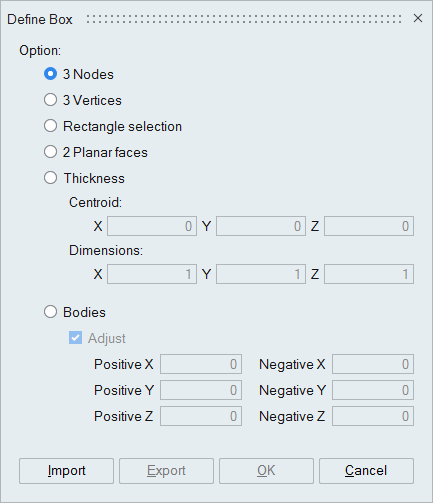
The box is used to define a cuboid region to define a mesh control for the entities or portion of entities falling inside the cuboid region. This can also be used to break the body using this cuboid.
Option
3 Nodes: Pick three non-collinear nodes to define a box. These nodes will form the center plane for the box. The box will be created using this plane.
3 Vertices: Pick three non-collinear vertices to define a box. These nodes will lie on the center plane of the box.
Rectangle selection: Left click on mouse and drag to define a box
2 Planar faces: Select 2 planar(either parallel or perpendicular) faces to define a box
Thickness: In this option, the dimensions of the box can be specified. Pick a node or vertex. This node or vertex will be the centroid of the box. The dimensions of the box can then be edited. Instead of picking a node or vertex, the coordinates of the centroid can be entered manually.
Box: Pick a Body to define the box.The dimensions of the box can be edited.
When the Adjust check box is:
- Turned ON, the box which is defined will be adjusted with some values
- Turned OFF, the box is defined by exactly bounding the selected bodies
Import
Saved box data can be imported to have the box at the same position.Export
After defining a box it can be exported and saved in the form of .xml file. Choose “Export” and save the box data.