Select Adjacent Layers
Description
This option is used to identify a group of faces, which forms critical areas in a model such as water jacket, combustion chamber of an engine block. When specific controls are to be applied over these areas, it would be tedious for the user to pick all these face groups manually and chances are there that some of the faces may be missed. In SimLab this process is automated in a way that with few clicks it is possible to get all the faces related to these critical areas.
This operator works by starting on one face and grows by adding the adjacent faces based on predefined rules. The rules include break angle and limit faces.
This tool is supported for both CAD and mesh models.
Dialog box

Face Selection
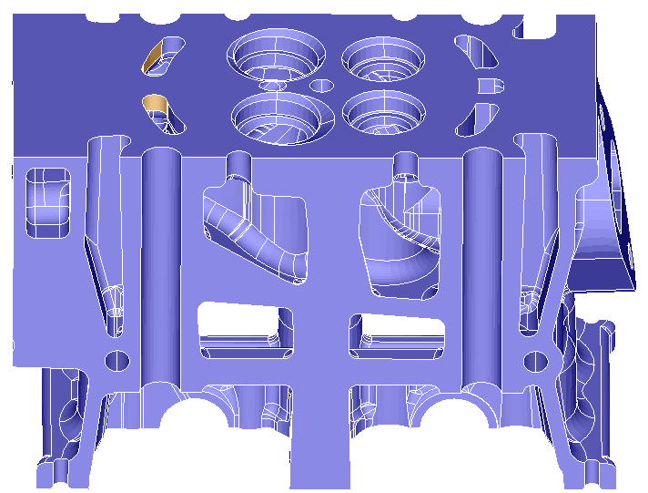
Guide face is a face from the group of faces to be identified. For example, a face from the water jacket area should be selected as Guide Face. With the guide face as reference, the tool will traverse along the model to identify its adjacent faces.
More than one guide face may be needed if the group of faces that we are interested in are disconnected. For instance, the combustion chamber area for each cylinder is disconnected. Hence one guide face from each combustion chamber should be selected.
Limit Selection
Limit faces are given to control the identification of the group of faces at a point. That is to say, if we need the group only up to a face, then we need to give that face as limit face. Resulting faces starts from guide face and grows up to the limit face (Non manifold edge). Edges that connect more than two faces are called as non-manifold edges.
Break angle specifies the included angle between two faces. By default, this angle is set to 45o. The adjacent faces whose included angle falls below the given break angle will be identified. This means all the adjacent faces whose angle is below 45o will be identified. If limit faces are specified, then the resulting selection will not have the faces beyond the limit faces. Angle option can be used with limit faces also.
All the planar, cylindrical and non-manifold faces can be given as limit faces. Check the "Add planar faces to Limit Faces" check box to add all the planar faces as limit face. The faces will be added automatically. Check the "Add cylindrical faces to Limit Faces" check box to add all the cylindrical as limit face. These two options will stop the traversal when it finds a cylindrical/planar face.
By default, non-manifold edges are considered as a limit for traversal. Uncheck the "Up to Non-Manifold edges" option to keep the selection beyond the non-manifold edges.
By default, adjacent faces include shared faces. Turn on the "Ignore shared faces" toggle to exclude them while collecting the adjacent faces. In the case of CAD-connected bodies, its primary use is to ignore the internal faces.
Create Group
Turn on the Create Group toggle to create a group and store the identified adjacent faces.
Limitation
-
Faces will be given as input for guide and limit face.
-
Always it creates the group with the name Adjacent_Faces, User defined name cannot be specified
Example
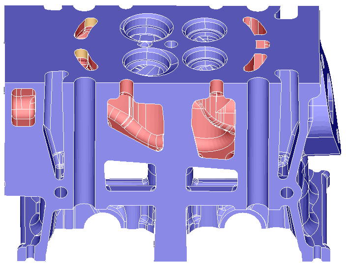
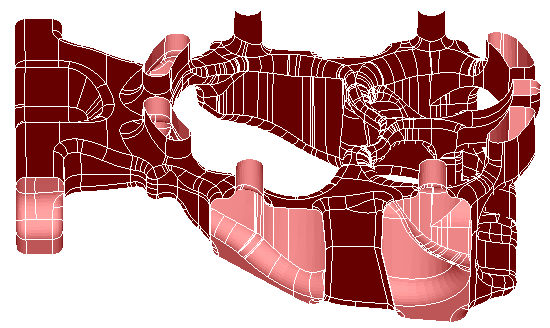
Pick the guide face and specify the break angle and click apply. The adjacent faces will be selected.
"Faces with surface normal on plane" toggle gets adjacent faces having surface normal on the defined plane. Plane can be defined using "Define/Modify Plane".