Cutting Plane Options
Introduction
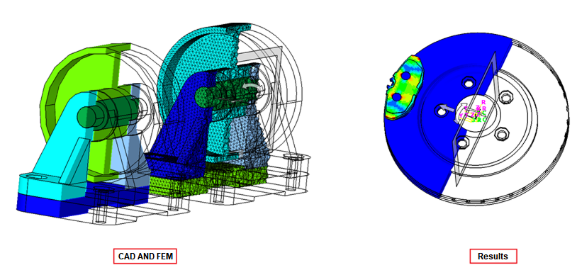
This option is used to manipulate the Cutting Plane to show the cut view of a solid model. Cutting Plane is primarily used to view the results on the solid elements. The Cutting Plane can be translated or rotated and options are available to aid the smooth transition of these movements. These options are available in a panel and will be displayed when the Cutting plane is enabled as shown below.
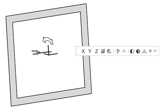
| Align to Global X Y Z axis |  |
Aligns the section plane to the x, y, or z-axis |
| Align Plane |  |
Enabling this option will open Align Plane dialog as shown in fig.(a).These options help positioning the cutting plane coplanar to nodes/elements/face/vertices/edges. |
| Reposition cutting plane to visible bodies center |  |
This option would reset the cut model in its default position based on the selected or visible entities. If the bodies are selected, the position of the cutting plane will be updated based on the selected bodies. Else, the position will be updated based on the visible bodies. |
| Flip cutting plane |  |
This option will reverse the visible part of the body i.e.,the elements of the body on the other side of the cutting plane will be visible. |
| Cut layer |  |
This option will show the layer of elements intersecting the cutting plane with the body in the wireframe display. |
| Face edges |  |
This option will display the face edges of the clipped part of the cutting plane. |
| Transparent faces | This option will display the elements in the clipped part of the cutting plane as transparent. | |
| Hide/Show cutting plane |  |
This option will show/hide the cutting plane manipulator. |
| More Options |  |
Enabling this option opens the More options dialog as shown in in fig.(b). |
Align Plane
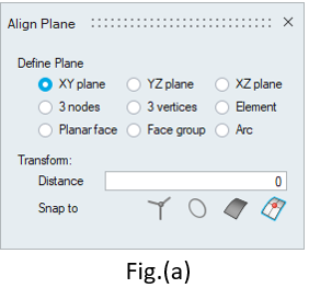
Define Plane
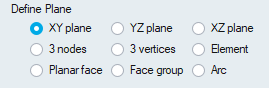
In XY, YZ and XZ options, the cutting plane will be created on the respective global planes.
3 nodes:
Pick three non-collinear nodes to define the cutting plane.
3 vertices:
Pick three non-collinear vertices to define cutting plane.
Element:
Pick an element to define cutting plane.
Planar face or Face group
Pick planar face to define cutting plane.
Arc
Pick an arc to define the cutting plane in arc's center.
Transform
Transform options move plane at the desired position. These options are disabled by default and get enabled once the cutting plane is aligned with any of the options under the define plane.
![]()
![]()
Distance:
Enter the value or place the cursor inside the Distance box and scroll the mouse. The cutting plane will be moved to this distance.
Snap to:
Vertex:
Pick a vertex to move the cutting plane to that point.
Node:
Pick a node to move cutting plane to that point.
Arc center:
Pick an arc to offset the cutting plane. The plane will be moved to the center of the arc.
Planar face
Pick a planar face to offset the cutting plane with the picked face.
More Options
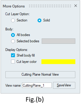
Cut Layer Option
Section cut
This option is used to see the shell elements of the cut section.
Solid cut
This option is used to see the solid elements of the cut section.
Body
All bodies
By default the cut section is shown for all bodies with All Body option.
Selected bodies
This option can be used to view the cut section of the selected bodies listed in the line edit.
Display Option
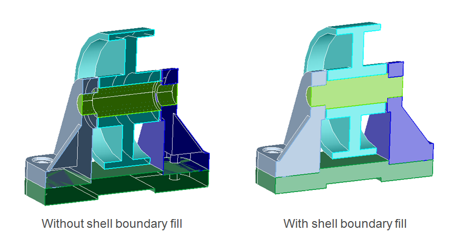
Shell body fill
This option used to fill the cutting section for FEM shell bodies and CAD solid bodies.
Cut layer color
By default, The elements which are intersected by cutting plane will be shown in body color.User can change the color of the cut section using this option.
Cutting Plane Normal View
This will align the cut section to normal view.Face Edges
This will display the face edges of the clipped part of the cutting plane.