
FORCE / ELFORCE
I/O Options and Subcase Information Entry Used to request structural element force output and elemental fluid particle velocity output for all subcases or individual subcases, respectively.
Format
FORCE (sorting, format_list, form, type, location, random, peakoutput, modal,statistics, average, SUBSYS, NLOUT) = option
Definitions
| Argument | Options | Description |
|---|---|---|
| sorting | <SORT1, SORT2> | This argument only applies to the PUNCH format (.pch file) or the
OUTPUT2 format (.op2 file file) output for normal modes,
frequency response, transient, linear static, nonlinear static small
displacement, and nonlinear static large displacement subcases. It
is ignored without warning if used elsewhere.
|
| format | <HM, H3D, OPTI, PUNCH, OP2, PLOT, HDF5, blank> |
|
| form | <COMPLEX, REAL,
IMAG, PHASE,
BOTH> Default (HM only) = COMPLEX Default (all other formats) = REAL |
|
| type | <TENSOR, DIRECT> | |
| location | <CENTER, CUBIC, SGAGE, CORNER, BILIN> |
|
| random | <PSDF,
RMS, PSDFC> No default |
|
| peakout | <PEAKOUT> Default = blank |
If PEAKOUT is present, only the filtered frequencies from the PEAKOUT card will be considered for this output. |
| modal | <MODAL> Default = blank |
|
| statistics | <STATIS, OSTATIS, or blank> | Element force statistics over time in a Transient Analysis are
controlled by this option. 15
|
| average | <AVG,
blank> Default = blank |
This option is only applicable for OPTI format.
Current support is limited to CBAR and
CBEAM elements.
|
| SUBSYS | <SUBSYS_ID> No default |
ID of the subsystem. When used along a subsystem definition, this option generates an individual result file for each subsystem with results for that subsystem only. For more information, refer to the SET Bulk Data Entry. |
| NLOUT | <NLOUT
ID> No default |
ID of the NLOUT Bulk Data Entry. For more information, refer to Comment 3 in the NLOUT Bulk Data Entry. |
| option | <YES, ALL,
NO, NONE,
SID> Default = ALL |
|
Comments
- If neither FORCE nor ELFORCE commands are present, then Force results or Fluid Particle Velocity results are not output. Fluid Particle Velocity results are currently only supported for H3D, OP2, and PUNCH formats.
- FORCE results are available for
ELAS (CELAS1, CELAS2,
CELAS3, CELAS4), ROD
(CROD), BAR (CBAR,
CBEAM), BUSH (CBUSH), PLATE
(CQUAD, CTRIA), GAP
(CGAP), FASTENER (CFAST)*, VISCOUS
DAMPER (CVISC), SCALAR DAMPER (CDAMP1,
CDAMP2, CDAMP3,
CDAMP4) and WELD (CWELD)
elements.
*CFAST elements or their corresponding force results are available for post-processing in HyperView only if the .fem file is loaded as a model. 10
- For implicit on-the-fly H3D output, ELFORCE is
available for ROD (CROD), BAR (CBAR,
CBEAM), BUSH (CBUSH), ELSA
(CELAS1, CELAS2), SCALAR DAMPER
(CDAMP1, CDAMP2), and VISCOUS DAMPER
(CVISC).
By default, the output for on-the-fly H3D is TENSOR. The DIRECT option must be explicitly specified if direct force output is required.
- The form argument is only applicable for Frequency Response Analysis. It is ignored in other instances.
- The forms BOTH and COMPLEX do not apply to the .frf output files.
- Multiple formats are allowed on the same entry; these should be comma separated. If a format is not specified, this output control applies to all formats defined by the OUTPUT command, for which the result is available.
- Multiple instances of this card are allowed. If instances are conflicting, the last instance dominates.
- For optimization, the frequency of output to a given format is controlled by the I/O option OUTPUT.
- In general, HyperView does not recognize the SORT2 format for results from the .op2 file. When results are output only in SORT2 format (<Result Keyword> (SORT2, OUTPUT2, ...)), the results are written by OptiStruct into the .op2 file in SORT2 format, but when the .op2 file is imported into HyperView, the results in SORT2 format are not recognized. Therefore, the SORT1 option is recommended for results output in OUTPUT2 format and SORT2 option is recommended for results output in PUNCH format.
- Vector and Tensor plots of some element force
results (weld, beam/bar and gap elements) are available for post-processing in
HyperView only if the .fem
file is loaded in the Load model field and the results file is loaded in the
Load results field (Figure 1 is an example illustration of the HyperView
Load model and results panel).Make sure that the Advanced option is selected from the Result Math template: menu.
Figure 1. 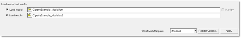
- For shell elements force results are given as force/unit length.
- format=OUTPUT2 can also be used to request results to be output in the Nastran output2 format (.op2 file).
- For Fluid velocity output, the Real and Imaginary
parts are calculated as: Where,
- Fluid density
- Acoustic pressure
- Frequency
- The Real part of the Fluid Velocity along the X-axis
- The Imaginary part of the Fluid Velocity along the X-axis
The Fluid Velocities in other directions (Y and Z) can be calculated similarly. Fluid velocity output in Coupled Frequency Response Analysis (Acoustic Analysis) refers to an elemental quantity and not a nodal/grid-based value.
- The HDF5 output is printed to a .h5 binary results file. For details of the supported analysis types and elements when the .h5 output format is requested, refer to the .h5 file.
- Element force statistics are
supported for Direct and Modal Linear Transient Analysis.
Only H3D output is supported for element force statistics and the output is available only for the following elements - CBAR, CBEAM, CELAS1, CELAS2, CONROD, CROD, CBUSH, CVISC, CDAMP1, CDAMP2, CGAP, CWELD, CGAPG and CSEAM.
The following statistics over time are output for Transient Analysis when STATIS or OSTATIS is specified.- Statistics
- Supported Element Force Result Types
- Minimum and Time of Minimum
- X-component, Y-component, Z-component
- Maximum and Time of Maximum
- Magnitude, X-component, Y-component, Z-component
- Absolute Maximum and Time of Absolute Maximum
- Magnitude, X-component, Y-component, Z-component
- Arithmetic Mean, Root Mean Square (RMS), Variance, and Standard Deviation
- Magnitude, X-component, Y-component, Z-component
The Element Force statistics can be viewed in HyperView after loading the H3D file, under Statistics over time option at the end of the timestep list in the Results Browser. Then, various statistics can be chosen from the sub-menu under Element Forces (1D) (Statistics) (s).Figure 2. 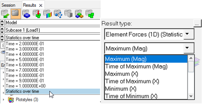
- On-the-fly computation of ELFORCE for shell elements (CQUAD4, CTRIA3, CTRIA6, CQUAD8) is supported for random response analysis when the underlying Frequency Response Function (FRF) plate force results are not required.