Bodies
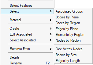
Select Menu
| FEM Body | CAD Body |
|---|---|
 |
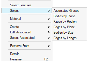 |
Associated Groups
This option is used to select the groups associated to the selected bodies.
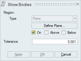
Bodies by Plane
This option is used to identify the bodies that lie above or below or on the plane.
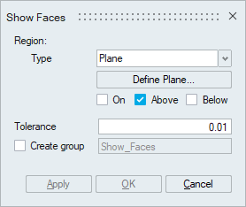
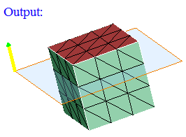
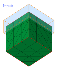
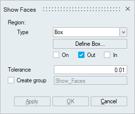
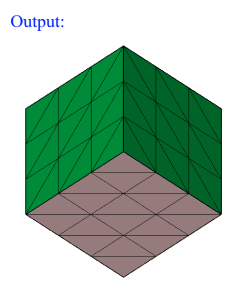
Faces by Region
This option works for the selected FEM/CAD bodies or faces. The faces will be displayed based on the defined region (Plane/Cylinder/Sphere/Box)
Checking the Create group creates a group containing the displayed faces.
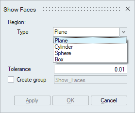
- Plane
Plane can be defined using the Define/Modify Plane option.
"On" option displays the faces that are lying on the defined plane. Distance (d) between the nodes of the face and the defined plane should be less than or equal to the given "Tolerance"."Above" option displays the faces that are lying above the plane (d > Tol).
"Below" option displays the faces that are lying below the plane (d > Tol).
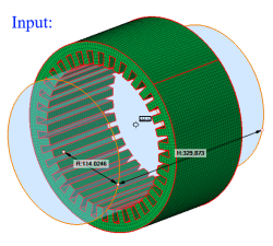
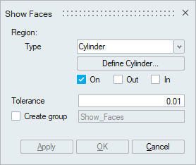
- Cylinder
Cylinder can be defined using the Define/Modify Cylinder option.
If all the nodes of a face and centroid of all the elements of a face are on the surface of a defined cylinder, then that face will be displayed using the On option. Let 'r' be the radius of the defined cylinder and 'd' be the distance between the node and the axis, then (r + Tol) >= d >= (r - Tol).If all the nodes of a face and centroid of all the elements of a face are lying outside of the defined cylinder and (d > r + Tol), then that face will be displayed using the Out option.
If all the nodes of a face and centroid of all the elements of a face are lying inside of the defined cylinder and (d < r - Tol), then that face will be displayed using the In option.
- Sphere
Sphere can be defined using the Define/Modify Sphere option.
If all the nodes of a face and centroid of all the elements of a face are on the surface of a defined sphere, then that face will be displayed using the On option. Let 'r' be the radius of the defined sphere and 'd' be the distance between the node and the center, then (r + Tol) >= d >= (r - Tol).If all the nodes of a face and centroid of all the elements of a face are lying outside of the defined sphere and (d > r + Tol), then that face will be displayed using the Out option.
If all the nodes of a face and centroid of all the elements of a face are lying inside of the defined sphere and (d < r - Tol), then that face will be displayed using the In option.
- Box
Box can be defined using the Define/Modify Box option.
If all the nodes of a face and centroid of all the elements of a face are on the surface of a defined box, then that face will be displayed using the On option. Let d be the distance between any one of the planes of the box and a node, then d <= Tol.
If all the nodes of a face and centroid of all the elements of a face are lying outside of the defined box and (d > Tol), then that face will be displayed using the Out option.If all the nodes of a face and centroid of all the elements of a face are lying inside of the defined box and (d > Tol), then that face will be displayed using the In option.
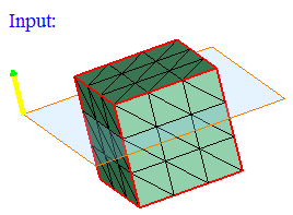
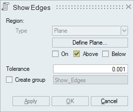
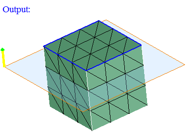
Edges by Plane
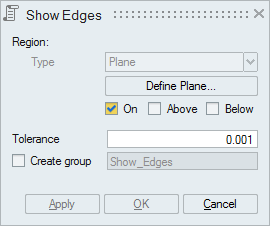
This option works for the selected FEM/CAD bodies or faces.
Plane can be defined using the Define/Modify Plane option.
"On" option displays the edges that are lying on the defined plane. Distance (d) between the nodes of the edges and the defined plane should be less than or equal to the given "Tolerance".
"Above" option displays the edges that are lying above the plane (d > Tol).
"Below" option displays the edges that are lying below the plane (d > Tol).
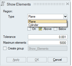
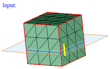
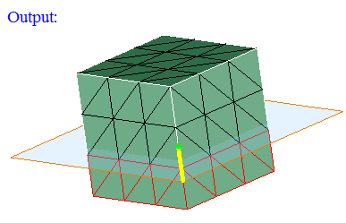
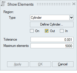
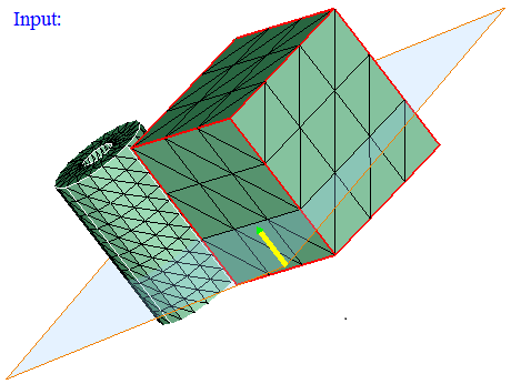
Element by Region
This option displays the elements based on the defined region (Plane or Cylinder). First select the type of region to be defined.
-
Plane
This option works for the selected FEM bodies or faces.
Plane can be defined using the Define/Modify Plane option.
"On" option displays the elements that are lying on the defined plane. Distance (d) between the nodes of the element and the defined plane should be less than or equal to the given "Tolerance".
"Above" option displays the elements that are lying above the plane (d > Tol).
"Below" option displays the elements that are lying below the plane (d > Tol).
If the elements found exceeds the number of elements entered in "Maximum elements" field, then the elements upto the maximum count will only be displayed. Remaining elements will not be displayed.
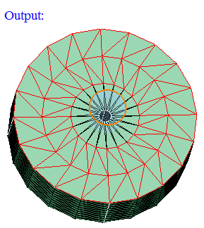
- Cylinder
This option works for the selected FEM bodies or faces.
Cylinder can be defined using the Define/Modify Cylinder option.
"On" option displays the elements that are lying on the defined cylinder. Let 'r' be the radius of the defined cylinder and 'd' be the distance between the nodes of the element and the axis, then (r+ Tol) >= d >= (r- Tol).
"Out" option displays the elements that are lying outside of the defined cylinder (d > r + Tol).
"In" option displays the elements that are lying inside the cylinder (d < r - Tol).
If the elements found exceeds the number of elements entered in "Maximum elements" field, then the elements upto the maximum count will only be displayed. Remaining elements will not be displayed.
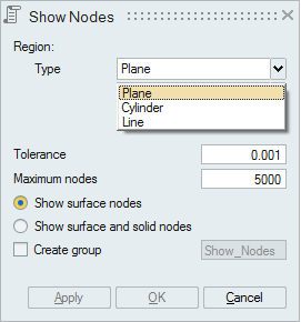
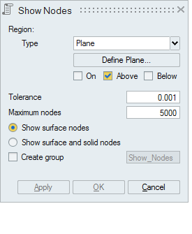
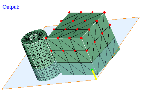
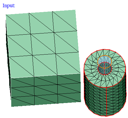
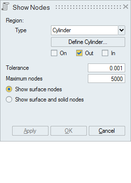
Nodes by Region
This option displays the nodes based on the defined region (Plane or Cylinder or Line). First select the type of region to be defined.
-
Plane
This option works for the selected FEM bodies or faces.
Plane can be defined using the Define/Modify Plane option.
"On" option displays the nodes that are lying on the defined plane. Distance between the node and the defined plane should be less than or equal to the given "Tolerance".
"Above" option displays the nodes that are lying above the plane. Distance between the plane and the node in the plane direction should be greater than the given "Tolerance".
"Below" option displays the nodes that are lying below the plane. Distance between the plane and the node in the opposite direction of the defined plane should be greater than the given "Tolerance".
Checking the "Show surface and solid nodes" option displays internal nodes in the selected solid body.
If the nodes found exceeds the number of nodes entered in "Maximum nodes" field, then the nodes upto the maximum count will only be displayed. Remaining nodes will not be displayed.
- Cylinder
This option works for the selected FEM bodies or faces.
Cylinder can be defined using the Define/Modify Cylinder option.
"On" option displays the nodes that are lying on the defined cylinder. Let 'r' be the radius of the defined cylinder and 'd' be the distance between the node and the axis, then (r+ Tol) >= d >= (r- Tol).
"Out" option displays the nodes that are lying outside (d > r + Tol) of the defined cylinder.
"In" option displays the nodes that are lying inside the cylinder (d < r - Tol).
If the nodes found exceeds the number of nodes entered in "Maximum nodes" field, then the nodes upto the maximum count will only be displayed. Remaining nodes will not be displayed.
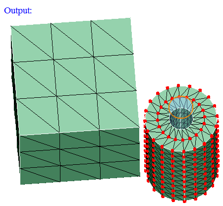
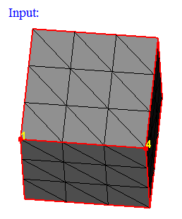
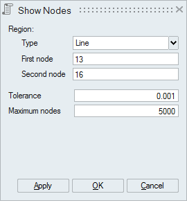
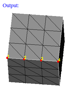
- Line
This option works for the selected FEM bodies or faces.
Line can be defined by selecting any 2 nodes. Set the focus on the "First Node" and select a node. And set the focus on the second node and select the another node defining the line.
Distance between the displayed nodes and the line should be less than or equal to the "Tolerance".
If the nodes found exceeds the number of nodes entered in "Maximum nodes" field, then the nodes upto the maximum count will only be displayed. Remaining nodes will not be displayed.
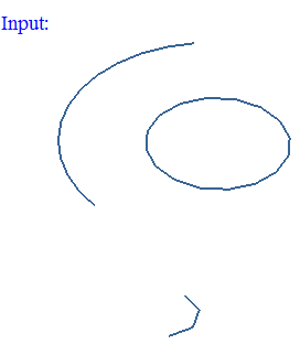
Free Vertex Nodes
This option displays the nodes in the free vertices of the selected wire body.
Bodies by Size
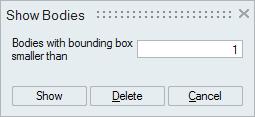
This option is used to identify small bodies. Bodies whose bounding box size is smaller than the user given size will be displayed.
- Show: This option show the bodies that are smaller than the user given bounding box size.
- Delete: This option is used to delete the bodies that are smaller than the user given bounding box size.
Edges by Length
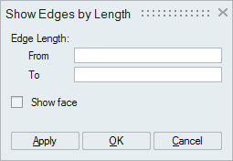
Select one or more bodies and specify the edge length range. The edges of the selected body within the specified range will be displayed.
If the "Show face" option is enabled, then the faces of those edges will be displayed.
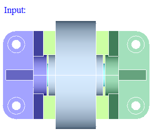
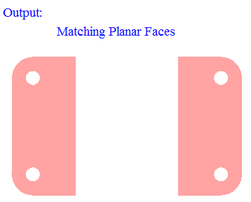
Overlapping CAD Faces
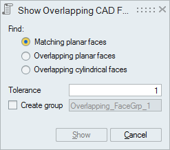
This option works for the selected CAD bodies. Atleast two bodies should be selected.
- "Matching planar faces" option displays the geom-matching planar
faces between the selected bodies.
- "Overlapping planar faces" option displays the planar faces that are overlapping between the selected bodies.
- "Overlapping cylindrical faces" option displays the cylindrical faces
that are overlapping between the selected bodies.
Distance between the displayed overlapping faces should be less than the given "Tolerance".

-
" Show " option is used to display the overlapping CAD faces between bodies. The overlapping CAD faces can be automatically stored in a face group. This is a temporary group and it will deleted during Redisplay or Reset.
- "Create group" option is used to add overlapping CAD faces in a
group. It creates group with user specified name. Before creating a group,
it will do duplicate check. If the faces are already present in any of the
group, it post a warning message to overwrite in the same group or
not.
Script support is added for this tool, It records the following details(Model Name, Body Name, Tolerance, Overlap Option (1->Matching Planar Faces, 2->Overlapping Planar Faces, 3->Overlapping Cylindrical Faces), Create(or)Show Group(1->Create, 0->Show), Group Name, UpdateDuplicates).