Point-Edge Sets - Advanced Design of Lattices and Other Truss Structures
A detailed description of how point-edge sets are used in Implicit Modeling within Inspire.
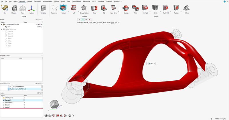
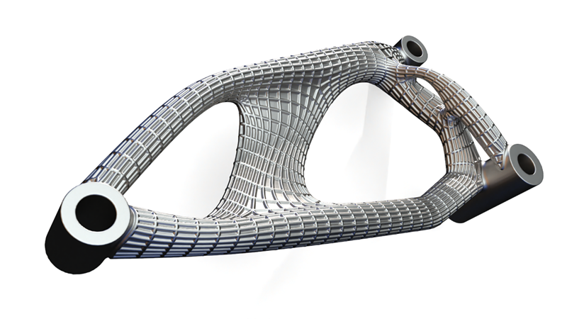
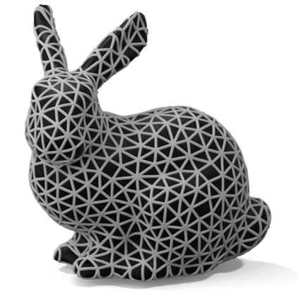
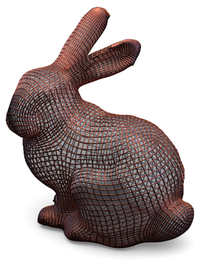
A remarkable number of engineering geometries can be derived from 3D points and edges between pairs of points. In Inspire Implicit Modeling, we call these point-edge sets (PES). You can leverage Inspire point-edge sets for advanced lattice design and the creation of other truss or strut-like structures.
What is a Point-Edge Set (PES)?
A description of point-edge sets in Inspire.
Mathematically inclined users recognize a point-edge set a directed graph. In Inspire Implicit Modeling, we describe a PES as a collection of 3D points and – optionally – a collection of edges that travel from a start point to an end point.
One way to think about an edge in a PES is that it represents a 3D line segment defined by a start and an end coordinate. While a PES may not have any edges – making something resembling a point-cloud – it must always have points.
Critically, a PES has no volume. The points are not spheres, and the edges are not cylinders or capsules. However, there are many ways to create volumes from a PES.
Is a Point-Edge Set a Field?
A comparison of point-edge sets and fields.
A point-edge set can be used as a field. Implicit Modeling can use the underlying field of an object to locally influence other implicit geometry.
For example, the thickness of the struts in a lattice can be a function of the distance to a reference plane. A PES emits a field and can be used in the same way. The field that it emits is the unsigned distance to the closest point on the PES structure, which will either be a point or a point along the span of an edge. The field is unsigned as neither the points nor edges have an interior, making all distances positive.
Starting a Design with a Point-Edge Set
An overview of designing with a point-edge set.
- Use the Point-Edge Set tool:

- Use one of the other Implicit Modeling tools that accept a point-edge set.
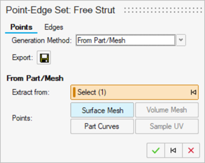
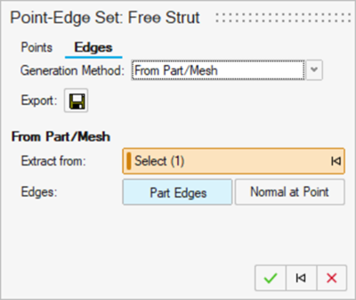
When creating or generating a PES, you will use the Points and Edges tabs in the guide panel to generate points and edges. Create points first, as edges cannot exist without points.
Differences Between Cell Strut Lattices and Point-Edge Sets
A comparison of cell strut lattices and point-edge sets.
Cell strut lattices and point-edge sets look very similar. However, cell strut lattices are computed differently for convenience and speed. The lattice is a repetition of predictable unit cells, and the entire structure is one entity – you cannot edit individual points and edges.
Cell strut lattices can be converted into a point-edge set, making each point and edge editable. This can be useful in advanced lattice design. In general, a point-edge set is a more flexible way of working. There are no strict requirements on the lattice layout, and points and edges are individual entities that can be edited.
Generating Points for a Point-Edge Set
Inspire Implicit Modeling provides multiple methods of generating points for a point-edge set.
| Option | Description |
|---|---|
| Uniform Random | Distribute points inside a body or its axis-aligned bounding box using uniformly distributed random points. Points can be restricted to be strictly inside, strictly outside, or on the surface of the body. |
| Minimum Spacing | Randomly place points inside a body or its axis-aligned bounding box while guaranteeing that no two points are closer than a specified (Euclidean) distance. Points can be restricted to be strictly inside, strictly outside, or on the surface of the body. |
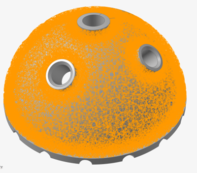
| From Part/Mesh | For CAD bodies (e.g. ParaSolid, STEP, etc.) and PolyNURBS bodies,
points can be extracted based on the vertices of a surface mesh
approximation of the object (various meshing settings are
available). They can also be generated by placing sampled points
along each feature curve (U sampling), or across each surface (UV
sampling) of the body. For triangle or quad mesh bodies (surface
meshes), points can be extracted based on the vertices of the
mesh. If Dual is selected, the points
extracted will be the barycenters of the triangle faces. For tetrahedral or hexahedral volume meshes, points can be extracted based on the vertices of the mesh. If Dual is selected, the points extracted will be the barycenters of the tetrahedrons/hexahedrons. If Dual + Surface is selected, than both the dual meshes of the surface and volume meshes will be generated. If
Dual + Surface Break is selected,
then any dual edges that pass over an edge between two surface
elements that exceeds the specified Break
Angle will split into two edges which pass
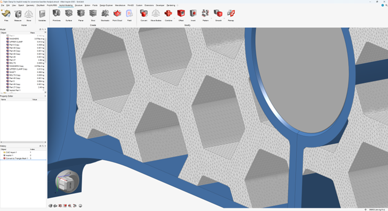
through the surface edge. 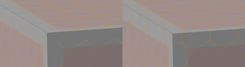 For bodies that are already cell strut lattices (via implicit modeling), the nodal positions of the underlying unit cells of that lattice can be extracted into a point-edge set. If an implicit modeling point cloud object has been created, these points can be extracted into a point-edge set. If the target is an implicit conform object, it is possible to sample the object with the Sample UV option. Depending on the dimensionality of the conform object, the U, V, and W parametrization can be sampled. |
| Import | Points created externally can be stored in a .csv file and then imported into the point-edge set. |
Generating Edges for a Point-Edge Set
Inspire Implicit Modeling provides multiple methods of generating edges for a point-edge set.
| Option | Description |
|---|---|
| No Edges | Force the point-edge set to contain only points (no edges). |
| Neighboring Points | Valence Connects each point to its 'k'
nearest neighbors, where 'k' can be a user-specified constant or a
field-driven property that varies in
space. Distance Connects each point to any point within the specified distance. The distance can be a user-specified constant or a field-driven property that varies in space. |
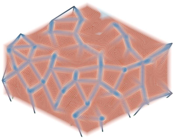
| Voronoi/Delaunay |
Treat each point in the point-edge set as a seed point in the creation of a 3D Voronoi diagram. Around each seed is a region that contains all locations that are closer to that seed than any other point in the PES. The edges exist where three neighbouring boundaries touch each other. The dual of the Voronoi diagram is the Delaunay tetrahedralization. In this case, edges are drawn between seed points whose Voronoi regions share a face. |
| From Part/Mesh | For CAD bodies (e.g. ParaSolid, STEP, etc.) and PolyNURBS bodies,
edges can be extracted based on the edges of a surface mesh
approximation of the object (various meshing settings are
available). They can also be generated by placing sampled points
along each feature curve (U sampling), or across each surface (UV
sampling) of the body. For triangle or quad mesh bodies (surface meshes), edges can be extracted based on the edges of the mesh. For tetrahedral or hexahedral volume meshes, edges can be extracted based on the edges of the mesh. Based on some initial points in a point-edge set, edges can be created based on each point and a vector. The vectors are derived from an implicit body (field) whose gradient supplies normal vectors (computed as the gradient of a scalar field). The points and the normal vectors define an infinite line, so you can specify the start and end locations of the edge along this line using the Start Distance and End Distance values (measured from the initial points, in the direction of the normal vector). Once complete, this will define the final set of points and edges in the point-edge set. For bodies that are already cell strut lattices (via implicit modeling), the edges in underlying unit cells of that lattice can be extracted into a point-edge set. |
| Import | Edges created externally can be stored in a .csv file and then imported into the point-edge set. There must be a correspondence between the edges defined in this .csv file and the points (imported via a separate .csv file). Specifically, the edges must reference the correct row index in the list of points. |
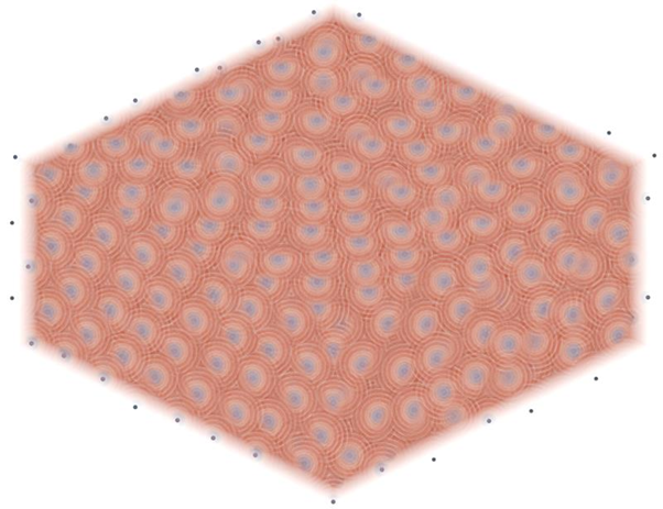
Why Would I Create a Point-Edge Set with No Edges?
An overview of the differences and applications of point clouds and a point-edge set with no edges.
There are visual similarities between point clouds (a different implicit modeling tool) and a point-edge set with no edges. However, their usage and utility are very different. The best way to differentiate the two is as follows:
| Point Cloud | Point-Edge Set (No Edges) |
|---|---|
| Primarily used as spatial influences to create fields and other field-driven effects and to place objects when using the pattern-to-point-cloud tool. They can also be used to manually sculpt geometry. | Primarily used to create structures, such as lattices and other circular or spherical bumps or perforations. |
| Each point is defined by six values: x-position, y-position, z-position, scalar value, radius of influence, and fall-off (a blend between the region of influence and the rest of space). | Each point is defined by three values: x-position, y-position and z-position position. |
| You can interpolate the scalar values attached to each point in a point cloud to create an entire field within some bounds. | There are no values associated with the points in a point-edge set to interpolate. |
| Points can be placed manually using the movement handles or by clicking on the surface of bodies. | Points cannot be placed using the movement handles or by clicking on the surface of bodies. |
Moving between these two different types can be useful. Points from point clouds can be extracted directly into a point-edge set. To go the other way, the points of a point-edge set can be exported to a .csv file and then reimported into a point cloud from the point cloud guide panel.
- You need points in an arrangement that is otherwise difficult to create, such as evenly or randomly spaced over a surface or volume or following feature curves.
- You need absolute control over which points to keep and which to reject from a set.
- You wish to create spherical bumps or perforations (cutouts) in a model.
Applying Filters to a Point-Edge Set
Filters allow you to specify whch points and edges you want to preserve in a point-edge set.
The real power of working with point-edge sets comes from the ability to filter the PES structure. A PES filter can operate on points or edges. A filter allows you to be very specific about which points and edges are preserved, removed, or altered in some other way.
PES filters only apply to a single PES. You can specify whether you want to act on the points or edges that pass the filter criteria or those that fail. Here is a list of filter types, with a brief description of their effects.
-
On the Implicit Modeling ribbon, select the
PES Filter tool.

Tip: To find and open a tool, press Ctrl+F. For more information, see Find and Search for Tools. - Type a Name to identify the filter.
- Use the Point-Edge Set collector to select the point-edge set you want to filter.
- Select Points or Edges to choose what the filter acts upon.
- Select Filter Pass or Filter Reject to choose whether points or edges are kept or removed if they meet the filter rules.
-
Choose a command from the Filter Points/Edges By
dropdown and adjust the filter rules as needed:
Filter Points By Description Bounding Body Keep or remove points that are interior to a bounding body. Field Value Keep or remove points based on the value of a reference field at the points’ locations. Valence Keep or remove points based on the number of edges that reference each point. Surface Snap Move points onto a reference surface based on their distance to that surface. Perturb Move points along a systematic or randomized vector. Angle At the location of each point, calculate the normal vector based on an implicit body or field. Specify an angular reference feature (line, plane, field) and compute the angle between the normal vectors at the points and the angular reference. Remove or preserve points based on the size of this angle on a point-by-point basis. Merge Merge points within a PES based on their distance to other points in the same PES. You can also optionally decide whether points should only merge if there is an edge connecting them. Filter Edges By DescriptionBoun Bounding Body Both ends and, optionally, the midpoint of each edge are checked to see if they are inside a bounding body. You can choose to remove an edge if any or all of the checked points are on the interior of the body. Length Edges can be kept/removed based on their individual lengths. Angle Each edge represents a vector from the start point to the end point. Specify an angular reference feature (line, plane, field, etc.) and compute the angle between the edge vector and the angular reference. Remove or preserve edges based on the size of this angle on an edge-by-edge basis. Field Value Keep or remove edges based on the value of a reference field at either end of the edge and, optionally, the midpoint. As with the Bounding Body edge filter, you can specify whether any or all of the checked points should pass/fail the filter. Manufacturability A combined filter that checks both angle and length at the same time. An edge must pass/fail the angle and the length check to be kept/removed. Trimming Specify a trimming body and split all edges that cross the trimming body (possibly multiple times) into interior and exterior sections. Specify whether you wish to keep the interior or exterior sections by using the Filter Pass and Filter Fail options. Note: The number of points and edges will change because of splits at surface crossings.Collapse Collapse edges that connect points within a specified Euclidean distance of each other. The two endpoints of the edge will be replaced by a single midpoint along the edge. Other edges that used to connect to either endpoint of the collapsed edge will now connect to the new midpoint. This filter applies this operation once across the entire PES. To complete further collapses will require additional Collapse filters. - Right-click and mouse through the check mark to exit, or double-right-click.
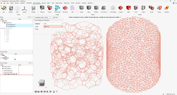
Applying Operators to Multiple Point-Edge Sets
You can use operators to combine or bridge point-edge sets.
-
On the Implicit Modeling ribbon, select the
PES Operator tool.

Tip: To find and open a tool, press Ctrl+F. For more information, see Find and Search for Tools. -
Choose a command from the Operator dropdown:
Operator Description Union Combines all the points into a single list and then also combines all the edges by referencing the correct points in the newly created list. Use the Target collector to select the point-edge sets you want to combine.
Bridge Bridges between two point-edge sets by creating new edges where one end of the edge comes from the first PES and the other end comes from the second PES. Use the Target collector to select the point-edge sets you want to bridge.
Use the Tool collector to select the point-edge sets you want to bridge with the selected targets.
Specify a Valence to set the number of nearest neighbors that will form edges between each point. This Valence property can be field-driven to change the number of connections that are formed in different locations.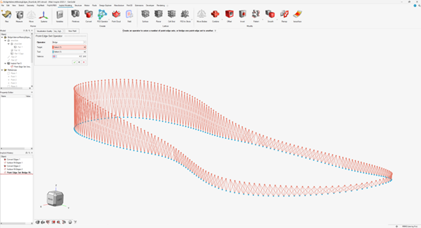
- Right-click and mouse through the check mark to exit, or double-right-click.
Adding Volume to a Point-Edge Set
Add volume to a point-edge set with the Point-Edge Set tool.
It may seem intuitive to add volume to a point-edge set using the
Offset tool in the Implicit Modeling ribbon. This will
work and can even use field-driven design to vary the thickness in different
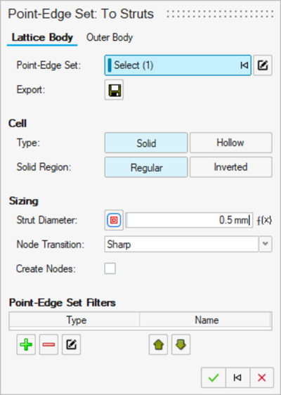
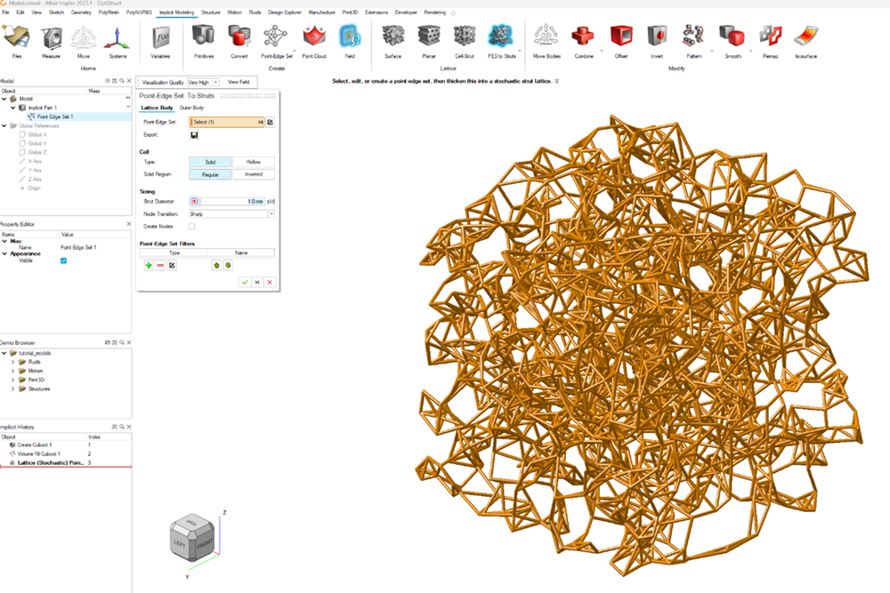
regions. However, we recommend using the Point-Edge Set to
Struts tool ![]() , or any lattice type that exists
in the dropdown beneath this tool.
, or any lattice type that exists
in the dropdown beneath this tool.
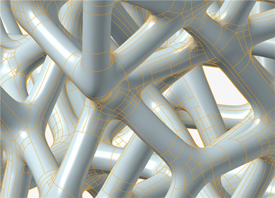
For clarity, adding volume to an edge (line segment) will create a capsule, which is a cylinder with spherical end caps. When you treat the PES like a lattice, many more options become available in a single, straightforward interface. Some examples of what you can do are listed below:
- Specify whether the edges become solid or hollow capsules (a cylinder with spherical caps).
- Specify whether you wish the volume to be the thickened edges or the volume resulting from the subtraction of the thickened edges from a solid version of the bounding box of the PES.
- Specify the edge (strut) diameters, possibly with field-driven design effects for gradients.
- Request fillets between edges where they join at points.
- Specify that points should be thickened into spheres, creating inflated nodes in the volume.
- Outer body treatments that put a shell around the lattice, or that join the lattice to another body using a combine operation (and more!).
Streamlined Workflows Using Point-Edge Sets
If you want all options present when you work with a point-edge set, you can create a PES using the Point-Edge Set Tool, before you convert this into a structure with volume.
This approach might show more information than is strictly necessary for your application. We have created some streamlined workflows for specific common design activities. These use PES behind the scenes, but show a greatly reduced set of options for their creation. The table and images below give a brief overview of these workflows:
| Name | Description | Example |
|---|---|---|
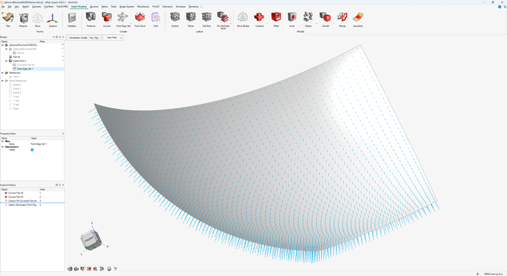
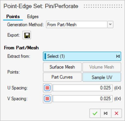
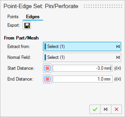
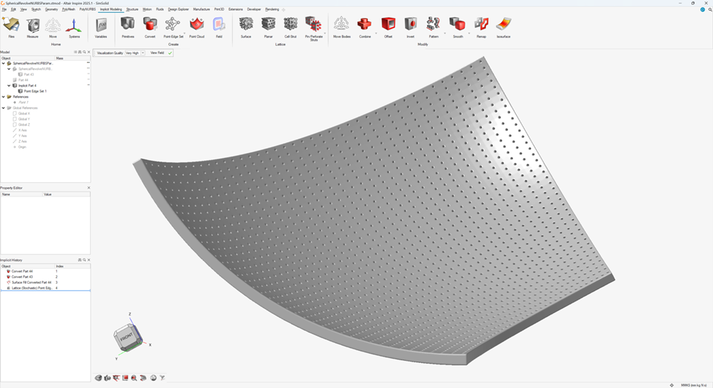
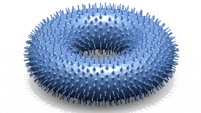
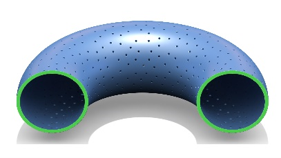
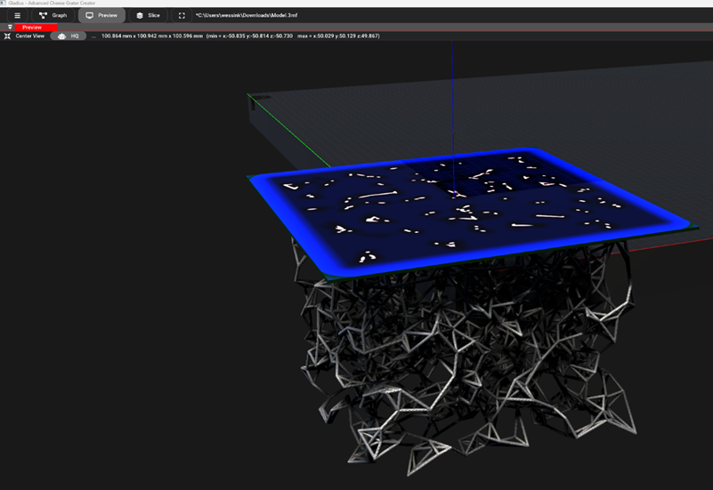
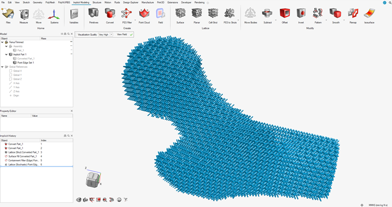
| Pin/Perforate |
This tool is dedicated to creating isolated edges (edges that
do not connect to each other). These can be used to create
pin-like features throughout a volume or on a surface.You
must supply a method of generating points to position the pins
and a field or feature that describes the orientation of the
pins. The orientations of the pins follow the gradient of a
selected field. In most cases, this gradient will produce
vectors normal to the surface for points that lie on the
surface. Finally, you specify the start and end distances
(from the generated points) that determine the length of the
pins. Note: Pins do not necessarily overlap the point that locates
them. |
  |
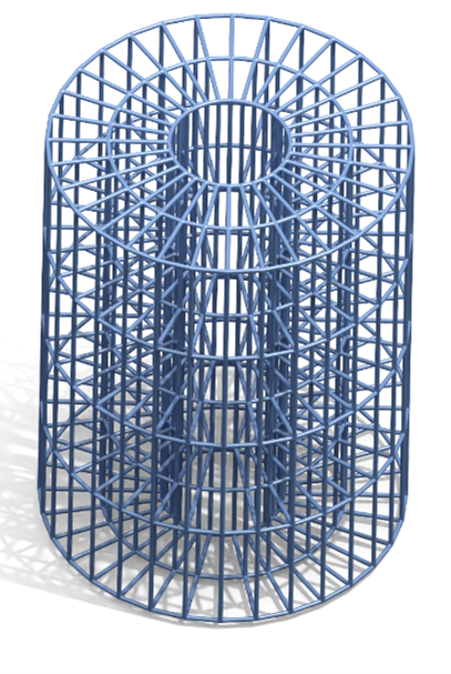
| Regular Grid |
Points will be created based on a regular grid in either a
Cartesian, Cylindrical, or Spherical coordinate system.
Additional points can be added using a custom cell type if
desired. The edges can be specified as one of the unit-cell
types available in the Cell-Strut tool
|
 |
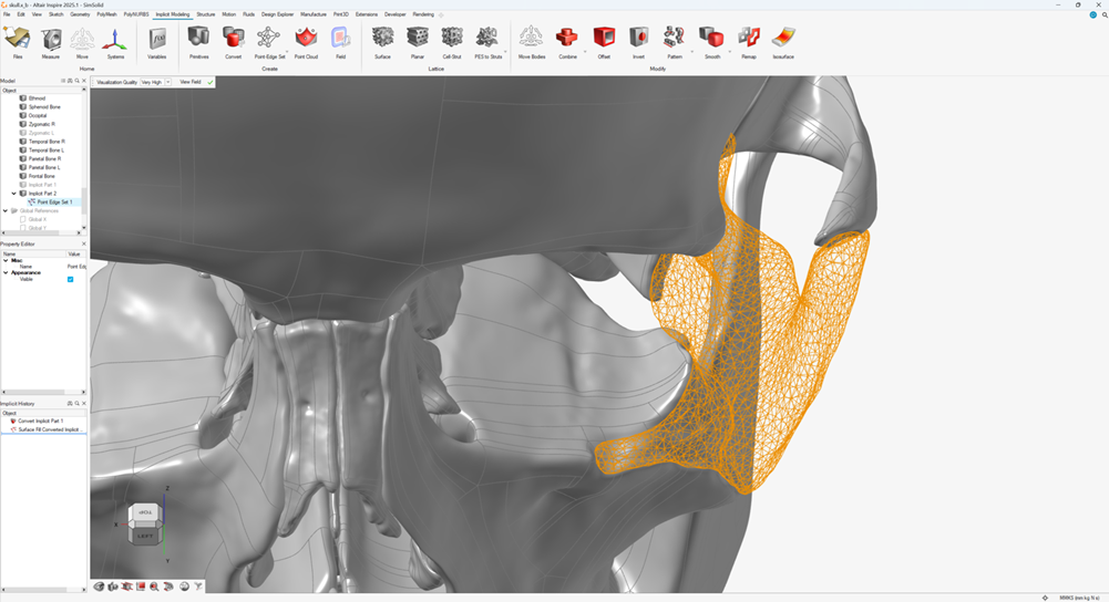
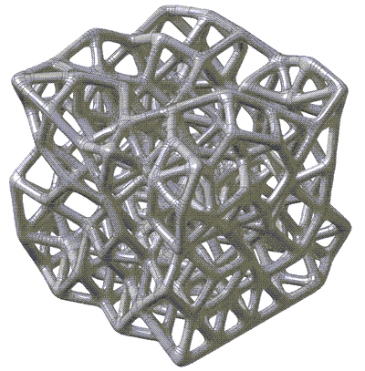
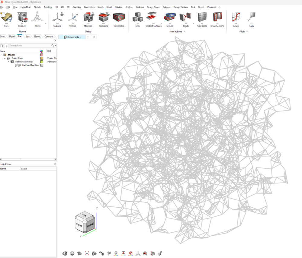
| Struts from Part |
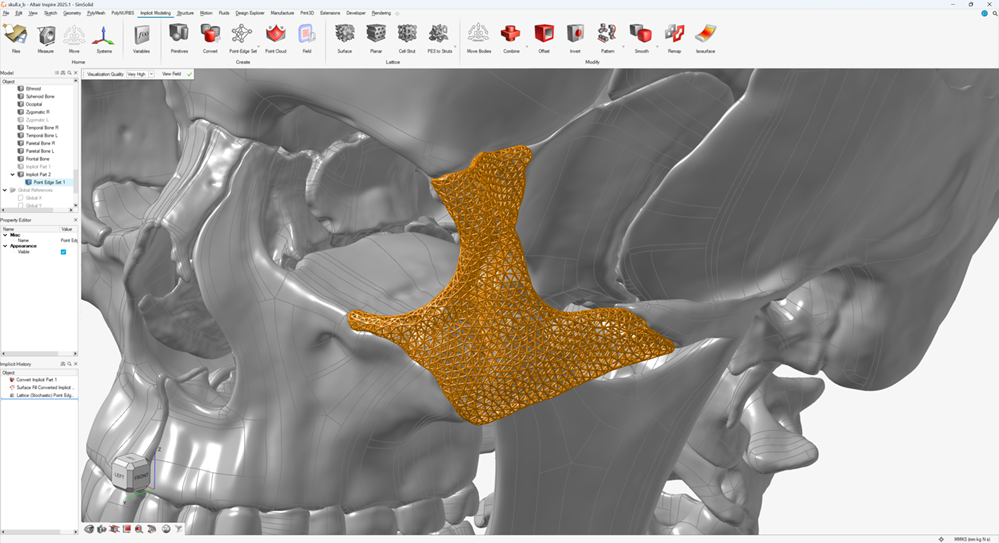
Points can be extracted from surface or volume mesh vertices (triangle, quad, tetrahedral, hexahedral, etc.), UV sampling of CAD surfaces and curves, or points in a point cloud. Edges can follow mesh edges, CAD feature curves, and also align to surface normal vectors or normal vectors extracted as the gradient of a field |
 |
| Import |
Import points — and optionally edges — from .csv files. |
   |
Exporting Designs with Point-Edge Sets
Exporting point-edge setings using the 3MF file format.
Implicit geometry can also be exported as a grid of scalar values (sometimes just the narrow band of the geometry close to the surface) using the OpenVDB format (*.vdb).
Concluding Remarks for Point-Edge Sets
Having read this article, you are now in a much better position to fully exploit the power of modelling with point-edge sets. By understanding the underlying structure and the use of filters, operators, and export options, you will be able to make informed choices regarding your modeling approach.
Specific workflow help can be found within the documentation for each of the operations and in the tutorial videos found in the documentation and on YouTube.
FAQs for Point-Edge Sets
Is a point-edge set a mesh?
No. A mesh typically has face or volume element information, and there is no such structure enforced in a PES. If you are trying to make a PES that resembles a surface or volume mesh, it may be better to create this mesh first (e.g. by converting a part to a triangle mesh) and then extracting the points and edges from this mesh in a PES.
If I’m extracting points or edges from a mesh, where do I find the controls for mesh sizing and accuracy tolerances etc.?
The mesh settings are specified on a part-by-part basis before you enter the implicit modeling context. To find them, make sure the Property Editor is shown (), and then edit the settings under the Mesh or CAD Facet sections of the part Properties.
Should I use the Point-Edge Set tool or one of the lattice tools for my design?
That is a matter of preference. A point-edge set is not a lattice unless you want it to become one. It could just be a field for utility purposes in another part of the design. You can do all of your design for the PES — including Filters and Operators — before you add volume to make it a lattice. Alternatively, the PES can be created when you enter one of the lattice Tools that use a PES. You can still apply filters in this version of the workflow, but you cannot apply operators from within a lattice context.
I have a single point or edge that I want to remove, but I cannot click on it and delete it. What should I do?
The individual elements are not selectable unless you can capture them using a PES Filter that isolates the point or edge that you are trying to remove. If you cannot make a filter that isolates the point or edge, you could export the PES to a .csv file, delete the point or edge manually from the .csv file, and then reimport the amended points and edges into a new PES.
What happens if I pattern a PES?
You can pattern a point-edge set. The result, however, will not be an expanded PES with more points and edges, nor will it create separately editable PES that you can use filters and operators on. It will simply create noneditable instances (copies) of the PES at different locations. If you edit the original PES before the pattern operation, these edits will appear in every instance of the PES after the pattern operation.
I want to have smooth blends between the struts (thickened edges) of my PES. Should I use the Smooth tool, the Fillet tool, or something else?
You can apply both smoothing and filleting operations (from the Implicit Modeling ribbon) to a PES that has been given volume. However, this is perhaps not the best way to get smooth transitions. Instead, you can enter one of the Lattice tools that uses PES and then change the Node Transition to Smooth, which will add a blending fillet between each strut (thickened edge) entering a point.
How do I remove hanging struts/edges that only connect to the wider PES structure at one end?
- Use a PES filter to remove all points with Valence
< 2. This will find all points that only have one edge attached to them
and delete them. This also removes any edges that reference this deleted
point. Note that removing points may produce new hanging edges, and you may
need multiple Valence < 2 filters.
- Use a PES filter to remove any edges that are not fully contained within the
bounding body of a lattice using the Bounding Body or
Field filter. This often works, but is less
reliable. Note that removing edges may produce new hanging edges, and you
may need multiple filters.
- To avoid awkward cuts where the bounding body of a lattice trims edges in an
undesirable way, you can create a lattice that extends beyond the bounding
body. Once created, delete points and edges that are far away from the
surface of the bounding body on the exterior. Then use a PES filter to
remove any points with Valence < 2. You can then
use the Surface Snap PES filter to move points that
are near the surface back onto the surface (closest point on the surface).
Discard any remaining points and edges that are exterior to the bounding
body for the lattice.
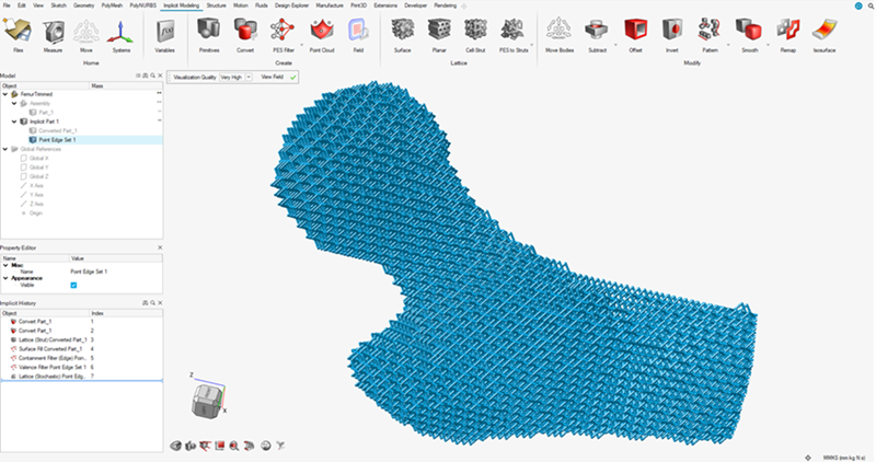
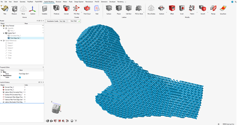
- In the Trimming PES filter for edges, there is an
option to close the trimmed edges. This will add new edges that connect
points that lie on the surface of the model (usually as a result of trimming
edges) in a triangulated fashion. These edges can either connect points
directly in a straight line, or can crawl over the surface (using lots of
smaller edges) to follow the contours of a model. There is also an option to
merge surface points that are very close together to the creation of short
edges for lattice closure.
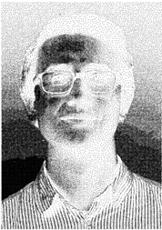
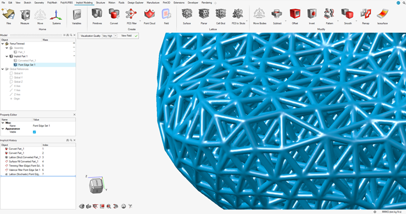
The following image shows a closeup of the closed lattice using the Direct connection option. All newly created edges between surface points are straight.
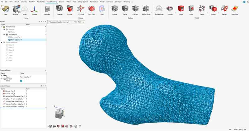
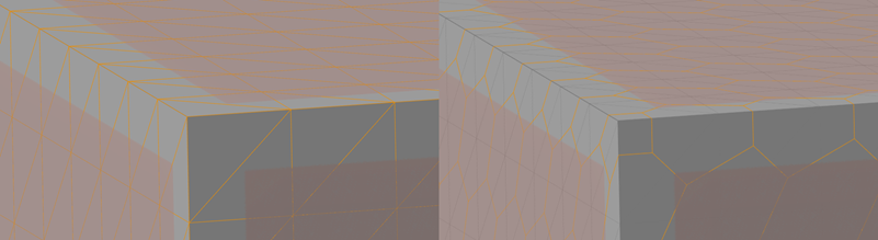
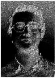
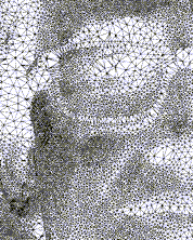
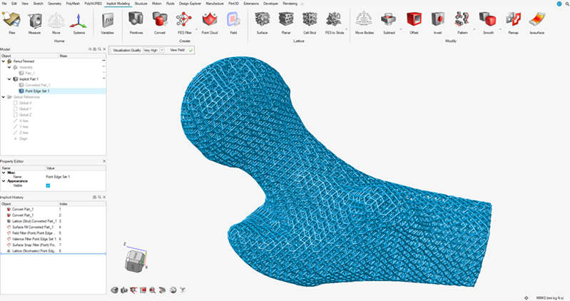
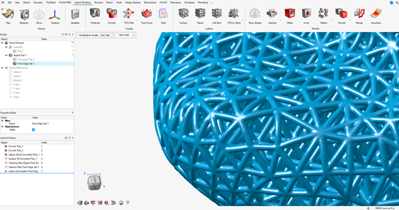
The following images show the closed lattice using the Surface Crawl connection option. All newly created edges between surface points are curved and conformal to the surface of the body.

Why did my PES disappear when I included it in a Boolean operation with another body/volume?
A PES is a collection of 0D and 1D entities i.e. points or edges with no volume. However, it also emits a field, where each point in space returns the distance to the closest point or point along an edge in the PES. It can therefore be used in Boolean operations. However, because the PES field has no interior, it may produce unexpected results.
What if I want to use a single face or curve from a nonimplicit geometry to create a PES?