Create an Implicit Midsurface
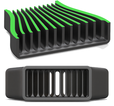
Create one or more surfaces or volumes that sit between two implicit bodies. This is useful for creating field-driven effects between two parts/surfaces or to create evenly spaced surfaces between two parts or surfaces.
-
On the Implicit Modeling ribbon, select the
Midsurface tool.

The Midsurface guide panel is displayed.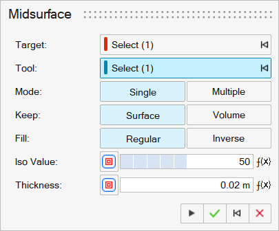
- Use the Target collector to select the implicit body that is the origin body of the midsurface.
- Use the Tool collector to select the implicit body that is the terminating body midsurface.
- Select Mode: Single or Multiple to create a midfield based on a single or multiple iso values between the tool and target bodies.
-
Select Keep: Surface to generate
a thickened isosurface between the target and tool. Select
Volume to set the field on one side of the isosurface
as solid.

-
Select Fill: Regular to generate
the default solid geometry regions (closest to the target), or select
Inverse to reverse the generated solid and voided
regions.
-
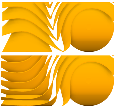
If Multiple is selected, set the origin and number of
evenly spaced midsurfaces to create.
- Select From: Medial Axis
to place the origin of the midsurface between the target and tool,
creating a symmetrical pattern. Select Target
Surface to set the origin of the midsurface at the
target. The difference between the two modes can only be seen when a
field is applied to the count parameter.
- Enter a value in the Count box to specify the
number of surfaces to place between the target and tool. The count can
be field driven.
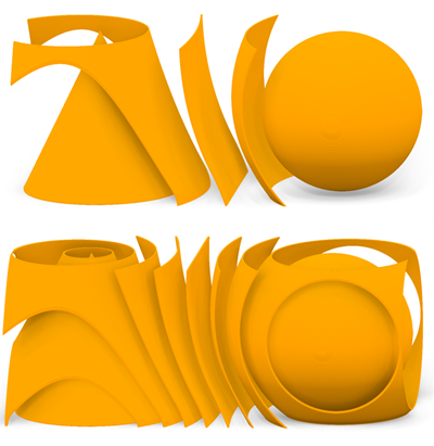
- Select From: Medial Axis
to place the origin of the midsurface between the target and tool,
creating a symmetrical pattern. Select Target
Surface to set the origin of the midsurface at the
target. The difference between the two modes can only be seen when a
field is applied to the count parameter.
-
If Single is selected, enter a value in the
Iso Value box to set the position of the midsurface.
The Iso Value is a percentage, where 0 is on the target
surface, and 100 is on the tool surface. The iso value can be field
driven.
-
Enter a value in the Thickness box to set the thickness
offset from the chosen Iso Value. The offset will be
symmetrical from the surface. The thickness value can be field driven.