
Create an Implicit Surface Lattice
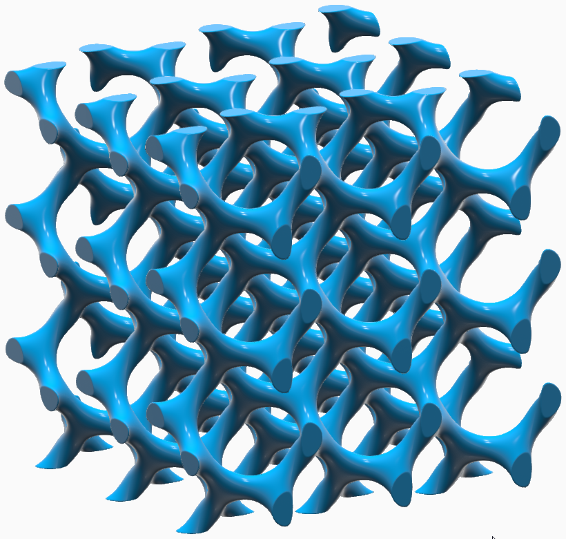
Fill a body with a surface lattice, which is a cellular structure constructed from one — or sometimes two — surfaces. The body can be a Parasolid, STL, PolyNURBS, or implicit geometry.
-
On the Implicit Modeling ribbon, select the
Surface Lattice tool.

Tip: To find and open a tool, press Ctrl+F. For more information, see Find and Search for Tools. - Optional: For Visualization Quality, select from Low to Very High quality, which corresponds to a low to very high density of elements. A higher quality produces sharper geometry features but is more computationally intensive. When creating a complicated function, it’s recommended to work using a lower quality and then switch to a higher quality after the function is complete.
- Select a body to fill with surface lattice. You can select a Parasolid, STL, PolyNURBS, or implicit geometry.
-
In the guide panel, select the Lattice Body tab.
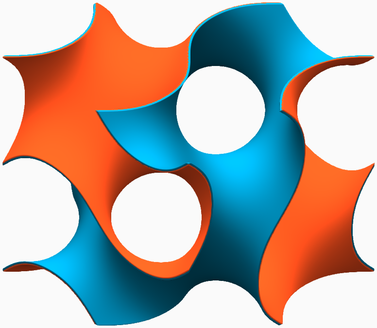
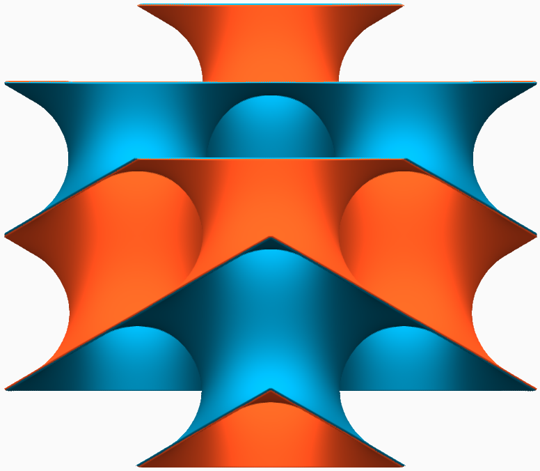
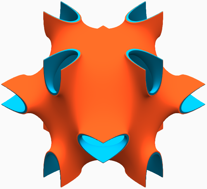
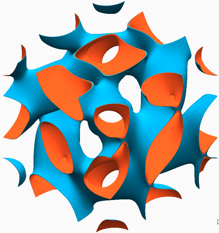
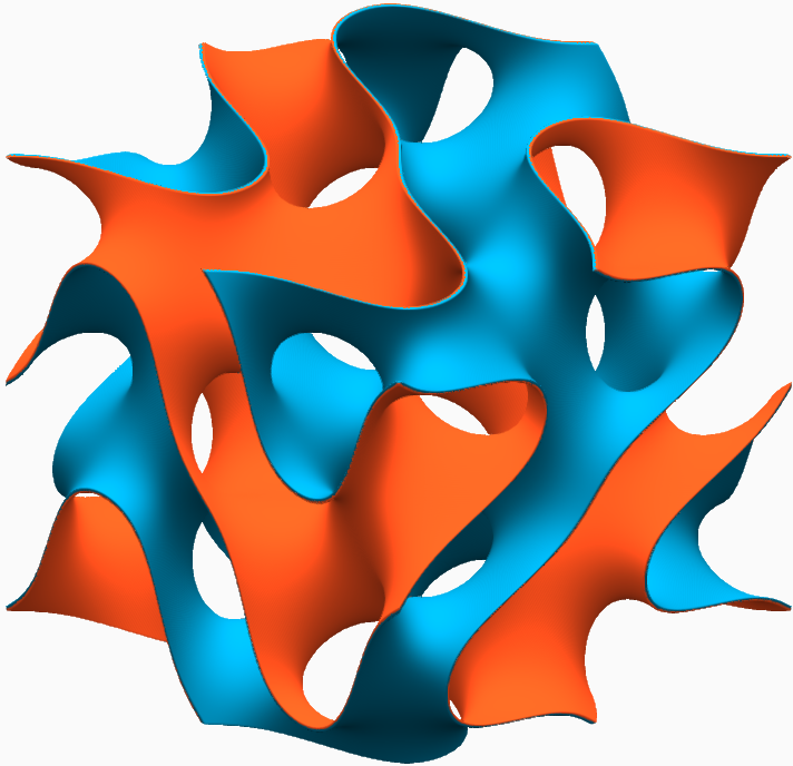
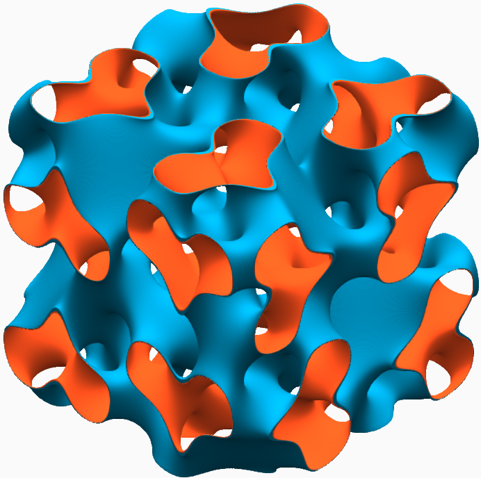
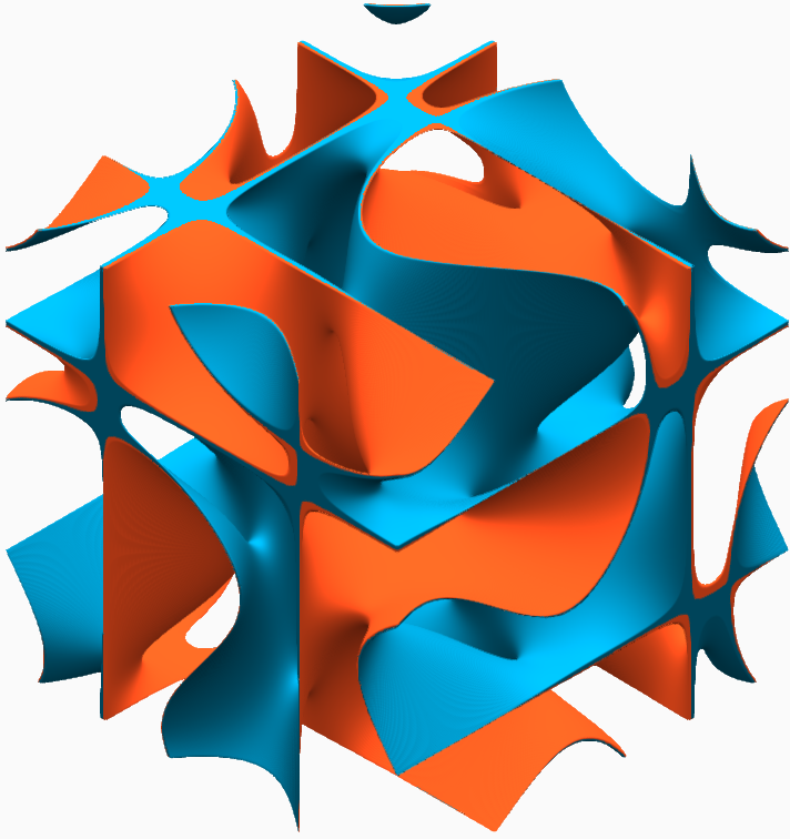
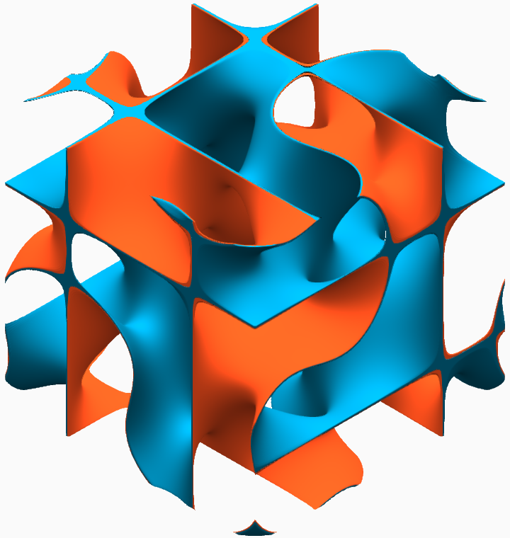
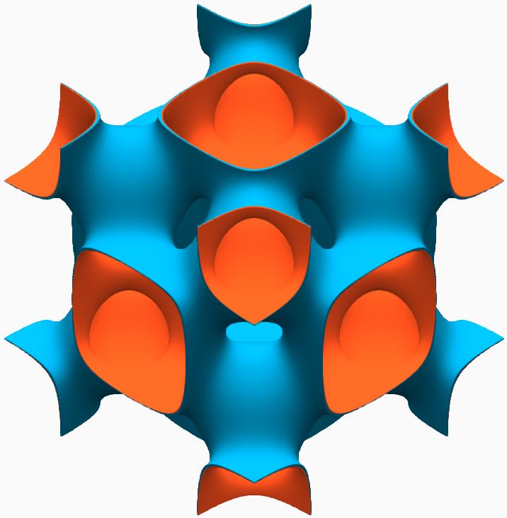
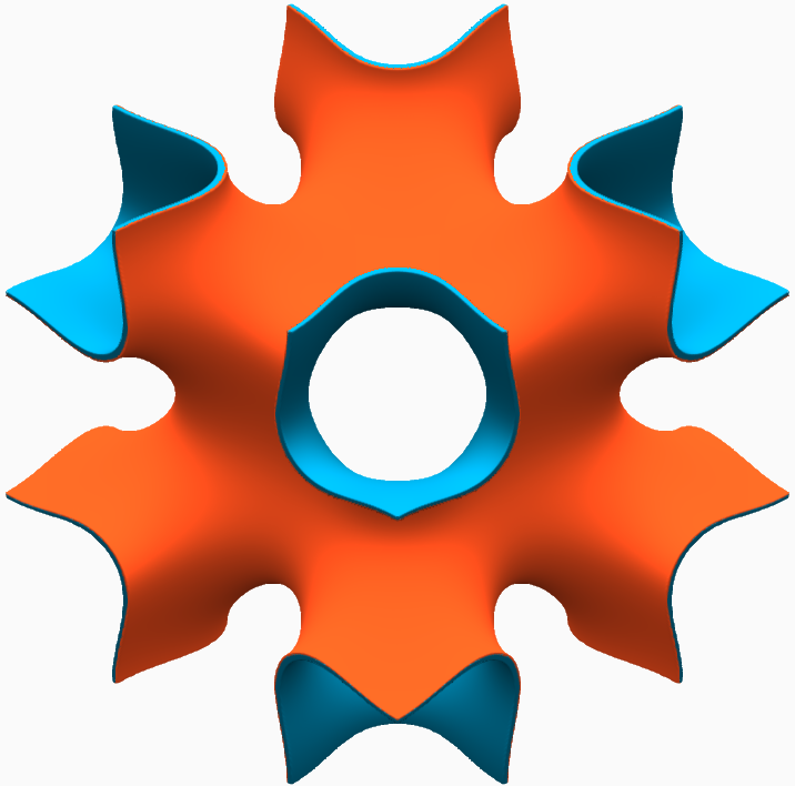
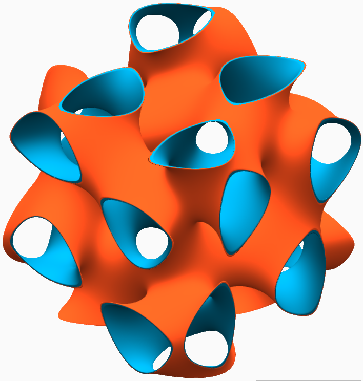
Option Description Surface - Unit Cell Select a unit cell type. In the following images, the surface that creates the lattice has been shown with blue coloring on one side of the surface and orange coloring on the other. These infinitely thin surfaces are transformed into solid volumes using the Surface Type options (Single and Double), which are described in the next section. - Gyroid
- Schwarz P
- Schwarz D
- Neovius
- Lidinoid
- Fischer Koch S
- Fischer Koch Cs
- Fischer Koch Y
- Fischer Koch Cy
- FRD
- IWP
- Split P
- Karcher K
- G Prime
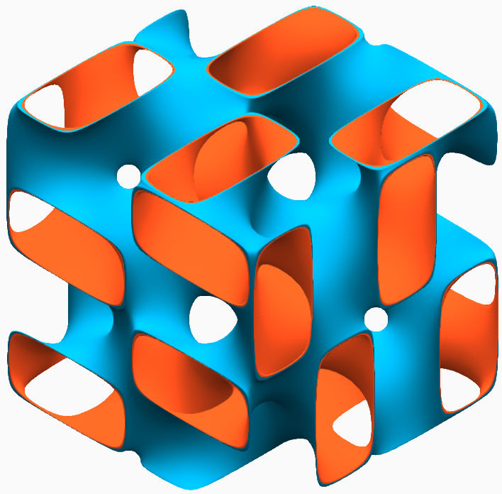
Surface - Type Select between a single or double surface lattice. - Single: Create a single, fully connected volume where one side of the surface is defined as being solid material.
- Double: Create a lattice with
two sides. In this case, two offset surfaces of the
same type are created, and the volume between the
surfaces is defined as being solid material. These
surfaces create two separate but interwoven pore
networks that are separated by the lattice volume.
This is useful for functions like heat transfer,
where you want the lattice to serve as a barrier
between two types of fluids.
Surface - Solid Region - Solid Region: Flip the solid and void domains of the lattice.
- Regular: Keep the solid and void domains of the lattice as-is.
- Inverted: Flip the solid and void domains of the lattice.
Coordinate System - Type Select a type of coordinate system. All three coordinate systems have three directions. - Cartesian (x, y, z)
- Direction 1 is x, which is linear.
- Direction 2 is y, which is linear.
- Direction 3 is z, which is linear.
- All three directions are orthogonal to each other.
- Cylindrical (r, θ, z):
- Direction 1 is r (radius), which is measured radially from the z-axis.
- Direction 2 is θ, which is angular about the z-axis where θ = 0 aligns to the x-axis.
- Direction 3 is z, which is linear.
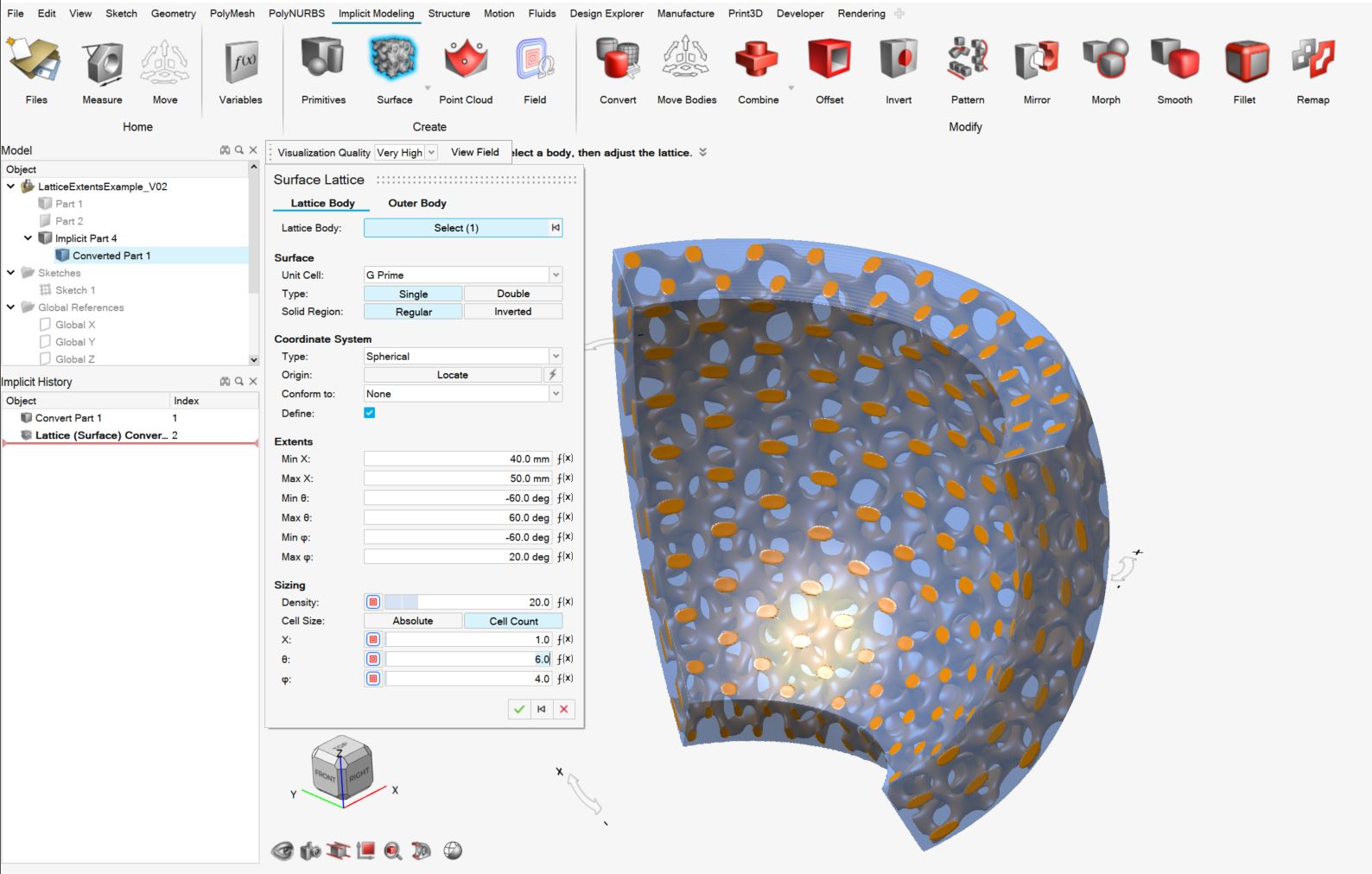
- Spherical (r, θ, φ):
- Direction 1 is r (radius), which is measured radially from the z-axis.
- Direction 2 is θ, which is angular and denotes azimuth (measured about the z-axis).
- Direction 3 is φ, which is angular and denotes elevation (measured relative to the XY plane).

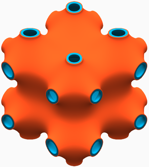
Coordinate System - Origin Locate: Use the Move tool to position and orient the local coordinate system of the lattice. Coordinate System - Conform to Conform to:use this option to generalize a Cartesian lattice by creating conformal (curved) spaces that operate on the parametrized coordinates, U, V and W. You can select an existing Conformal Coordinate Space from the dropdown menu or create a new one. For more information, see Create a Conformal Coordinate Space. Coodinate System - Define Extents Define: Using the input fields for on-screen handles, define the minimum and maximum extents of each of the coordinate directions (Cartesian: x, y, z; Cylindrical: x, θ, z; Spherical: x, θ, φ). You can then specify the number of unit cells that will span these extents by sizing them according to 'Count', or you can specify an 'Absolute' unit cell size in length units.
When using 'Count' for unit cell sizing, you are guaranteed to have precisely the specified number of unit cells spanning the extents. If the count is an integer, the unit cells will begin and end perfectly on the boundaries of the extents (see the images below for an example in a spherical coordinate system)
In case of absolute sizing, unit cells are guaranteed to begin on the minimum extent of each coordinate direction but they are not guaranteed to terminate nicely on the upper extent of each direction.

Sizing - Fill Type When working with the Double surface lattice type, you can choose between filling the unit cell solid volume as a relative volume fraction with Density or absolute amount with Thickness. Sizing - Density - Drag the slider or enter a value to define the relative density of the lattice as a percentage.
- Assign a variable.
- Apply a field.
Sizing - Thickness - Drag the slider or enter a value to define the thickness of the lattice wall between the two void domains.
- Assign a variable.
- Apply a field.Note: Due to the nonlinear nature of surface lattice equations, the thickness is technically an approximate value. The thickness should be very accurate near the nonthickened surface and may lose tolerance further away from the nonthickened surface.
Sizing - Cell Size Choose between defining the lattice size by an absolute dimension or the number of cells. - Absolute: Enter an absolute length value, or an absolute angle value, for non-Cartesian coordinate systems, along each axis.
- Cell Count: Enter the number of cells along each axis.
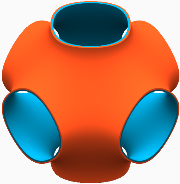
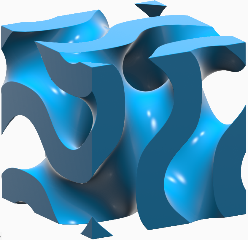
Bias When working with the Double surface lattice type, drag the slider or enter a value to vary the volumes on either side of the lattice, without changing the volume of the lattice itself. When you change the surface type to Double, there is a volume on one side of the lattice surface and a separate volume on the other side. The bias allows you to make one of those volumes smaller and the other larger without changing the amount of volume that the lattice itself takes up.
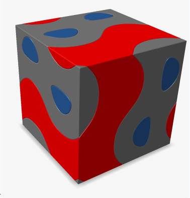
In this image, the lattice volume is gray, the volume on one side is blue, and the volume on the other side is red.Note that blue is appreciably smaller than red, hence "bias."
This mostly applies to situations where you have two fluids that are separated by a wall (lattice). Two-fluid heat exchangers are a good example of where this is helpful.
Sizing - Uniform (Cartesian Only) Make the unit cell dimensions equal along the x-, y-, and z-axes. X (Cartesian Only) - Enter the cell size or count along the x-axis.
- Assign a variable.
- Apply a field.
Y (Cartesian Only) - Enter the cell size or count along the y-axis.
- Assign a variable.
- Apply a field.
Z (Cartesian and Cylindrical Only) - Enter the cell size or count along the z-axis.
- Assign a variable.
- Apply a field.
θ (Cylindrical and Spherical Only) θ is angular about the z-axis where θ = 0 aligns to the x-axis. φ (Spherical Only) φ is angular and denotes elevation (measured relative to the XY plane). - Gyroid
-
Select the Outer Body tab.
- Select a type of outer body that will surround the surface lattice.
- None: Don't create an outer body.
- Shell: Create a closed offset shell around the
lattics with an optional trimming body.
Option Description Direction Select an offset direction for the shell. - Outward: Offset the shell outward from the lattice, increasing the size of the overall object.
- Inward: Offset the shell inward, consuming some of the lattice but maintaining the overall dimensions of the lattice.
- Both: Offset the shell both inward and outward.
Symmetry Symmetrically offset the shell inward and outward by the same distance. Outer Thickness Define the outward shell's offset thickness. You can directly enter thickness, controlled with a variable, or controlled in each position in space using a field (field-driven design). Inner Thickness Define the inward shell's offset thickness. You can directly enter thickness, controlled with a variable, or controlled in each position in space using a field (field-driven design). Trimming Body Select a body that's used to trim the shell. Use this to trim areas of the shell, which is useful for fitting the lattice and its shell into a predefined volume, or when you want to expose some of the lattice so that it is not covered by a shell. Transition Choose the type of transition between the outer body and lattice body. - Sharp: The lattice abruptly joins the surrounding shell.
- Fillet: The lattice blends into the surrounding shell using a fillet. If you select this option, define the fillet Radius.
- Chamfer: The lattice blends into the surrounding shell using a chamfer. If you select this option, define the chamfer Distance. For Fillet, the distance is the radius of the fillet and, for Chamfer, the distance is the setback of the chamfer. You can directly enter the distance, controlled with a variable, or controlled in each position in space using a field (field-driven design).
- Combine: Combine the outer body with the lattice
body, directly, without creating a shell that surrounds the
lattice.
Option Description Combine Body Select a body to combine the surface lattice with. This body should be adjacent to, or overlap with, the lattice. Transition Choose the type of transition between the outer body and lattice body. - Sharp: The lattice abruptly joins the surrounding outer body.
- Fillet: The lattice blends into the outer body using a fillet. If you select this option, define the fillet Radius.
- Chamfer: The lattice blends into the outer body using a chamfer. If you select this option, define the chamfer Distance. For Fillet, the distance is the radius of the fillet and, for Chamfer, the distance is the setback of the chamfer. You can directly enter the distance, controlled with a variable, or controlled in each position in space using a field (field-driven design).
- Click OK.