
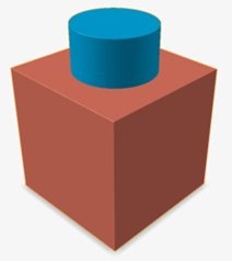
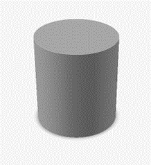
Intersect Implicit Geometry
Retain only the intersecting portions of two sets of implicit bodies.
You will select two sets of implicit bodies, which must to intersect.
- Targets are the first set of bodies.
- Tools are the second set of bodies.
-
On the Implicit Modeling ribbon, select the
Intersect tool.

Tip: To find and open a tool, press Ctrl+F. For more information, see Find and Search for Tools. - Optional: For Visualization Quality, select from Low to Very High quality, which corresponds to a low to very high density of elements. A higher quality produces sharper geometry features but is more computationally intensive. When creating a complicated function, it’s recommended to work using a lower quality and then switch to a higher quality after the function is complete.
- Select one or more target bodies.
- Select one or more tool bodies.
-
In the guide panel, select a type of Transition:
- Sharp
- Fillet: If you selected this option, define the fillet Radius. The fillet radius can be entered directly, controlled using a variable or driven by a field (field-driven design)
- Chamfer: If you selected this option, define the chamfer Distance. The setback of the chamfer can be entered directly, controlled using a variable or driven by a field (field-driven design).
- Click OK.