
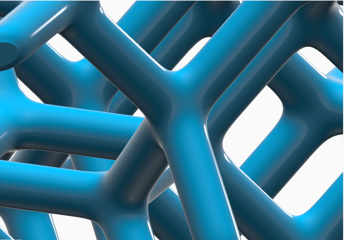
Create an Implicit Strut Lattice
Fill an implicit body with a strut lattice, which is constructed from nodes that are connected by beams.
-
On the Implicit Modeling ribbon, select the
Strut Lattice tool.

Tip: To find and open a tool, press Ctrl+F. For more information, see Find and Search for Tools. - Optional: For Visualization Quality, select from Low to Very High quality, which corresponds to a low to very high density of elements. A higher quality produces sharper geometry features but is more computationally intensive. When creating a complicated function, it’s recommended to work using a lower quality and then switch to a higher quality after the function is complete.
- Select a body to fill with strut lattice. You can select a Parasolid, STL, PolyNURBS, or implicit geometry.
-
In the guide panel, select the Lattice Body tab.
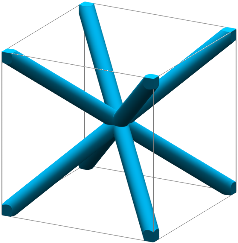
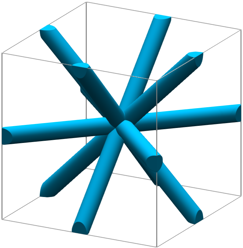
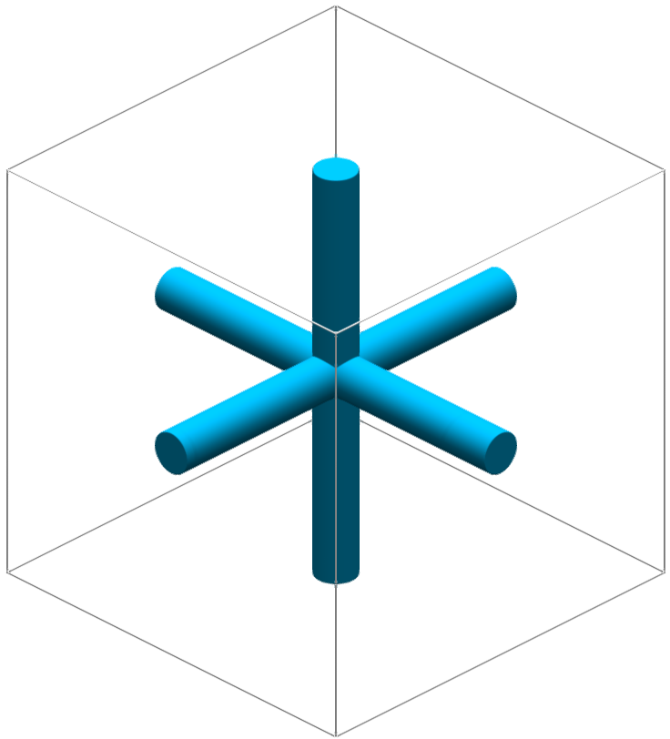
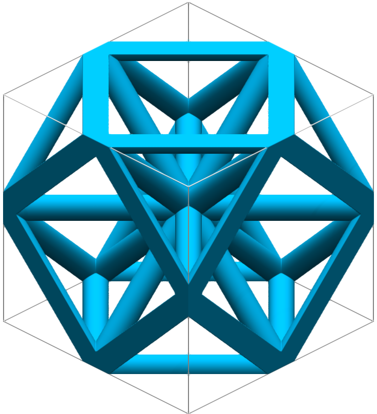
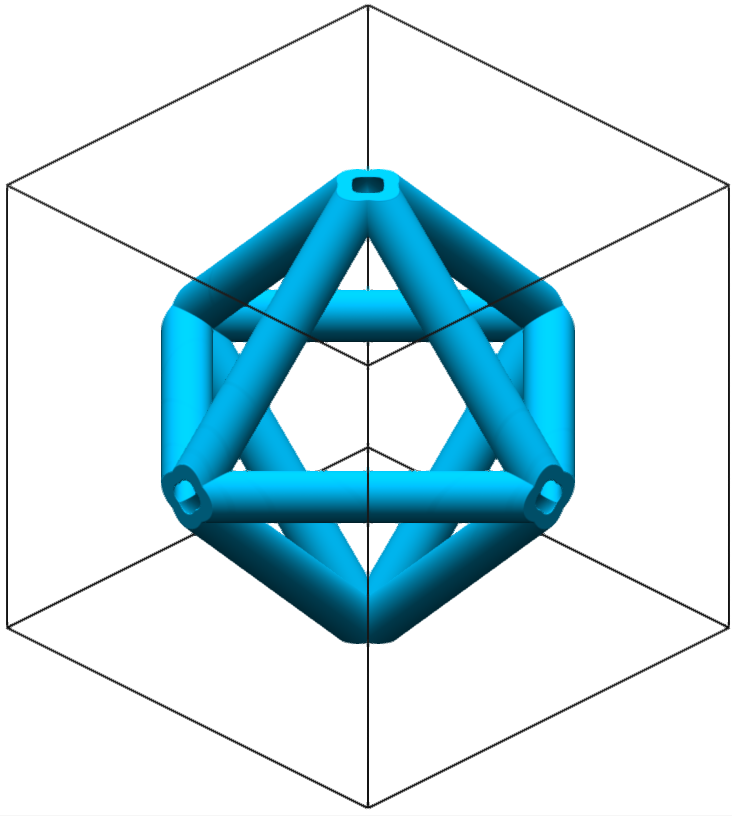
Option Description Cell - Type Select a cell type. - Body-Centered Cubic
- Face-Centered Primitive
- Face-Centered
Cubic
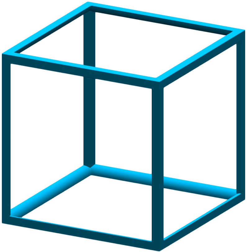
- Cubic Primitive
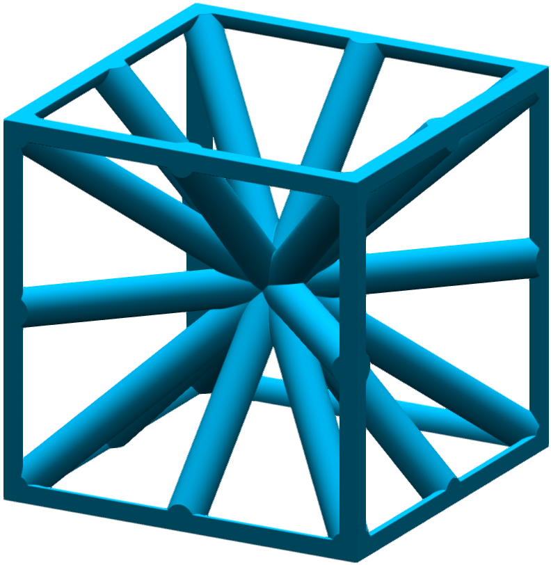
- Isotruss
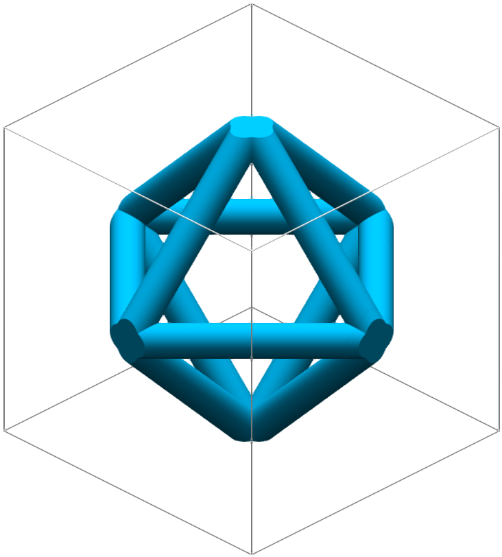
- Octagon
- Hex Truss
- Kelvin Cell
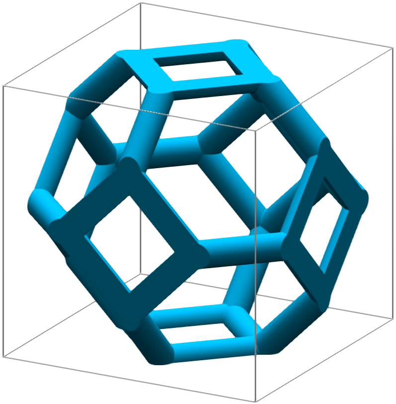
- Flourite
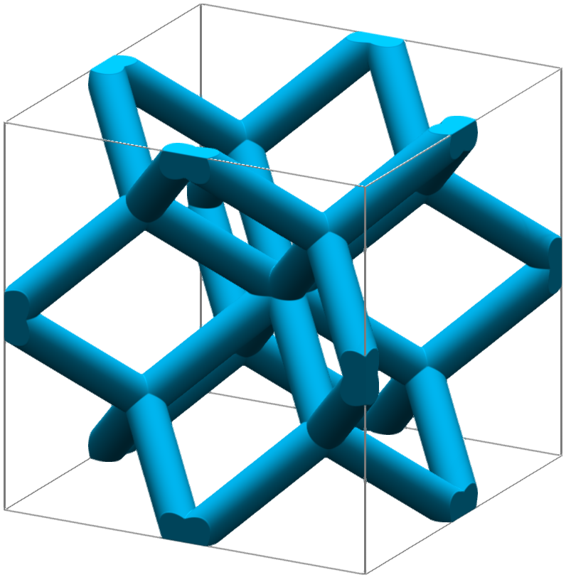
- Diamond
- Truncated Cube
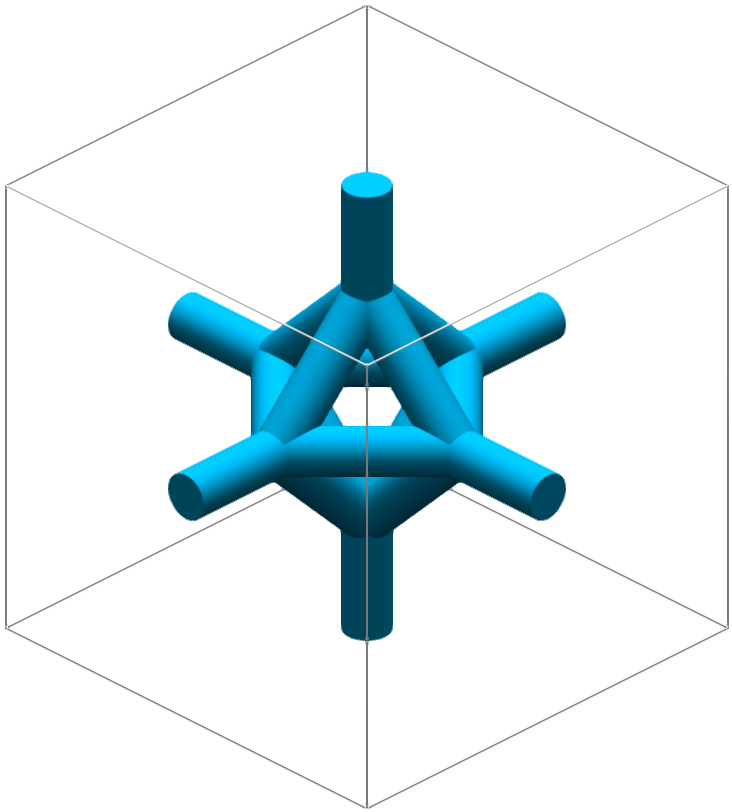
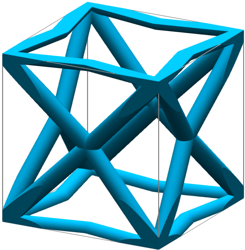
- Octet
- Create Unit Cell
Selecting this option will open the Unit Cell editor to start creating a new strut lattice unit cell. For more information, see Create a Custom Strut Unit Cell.
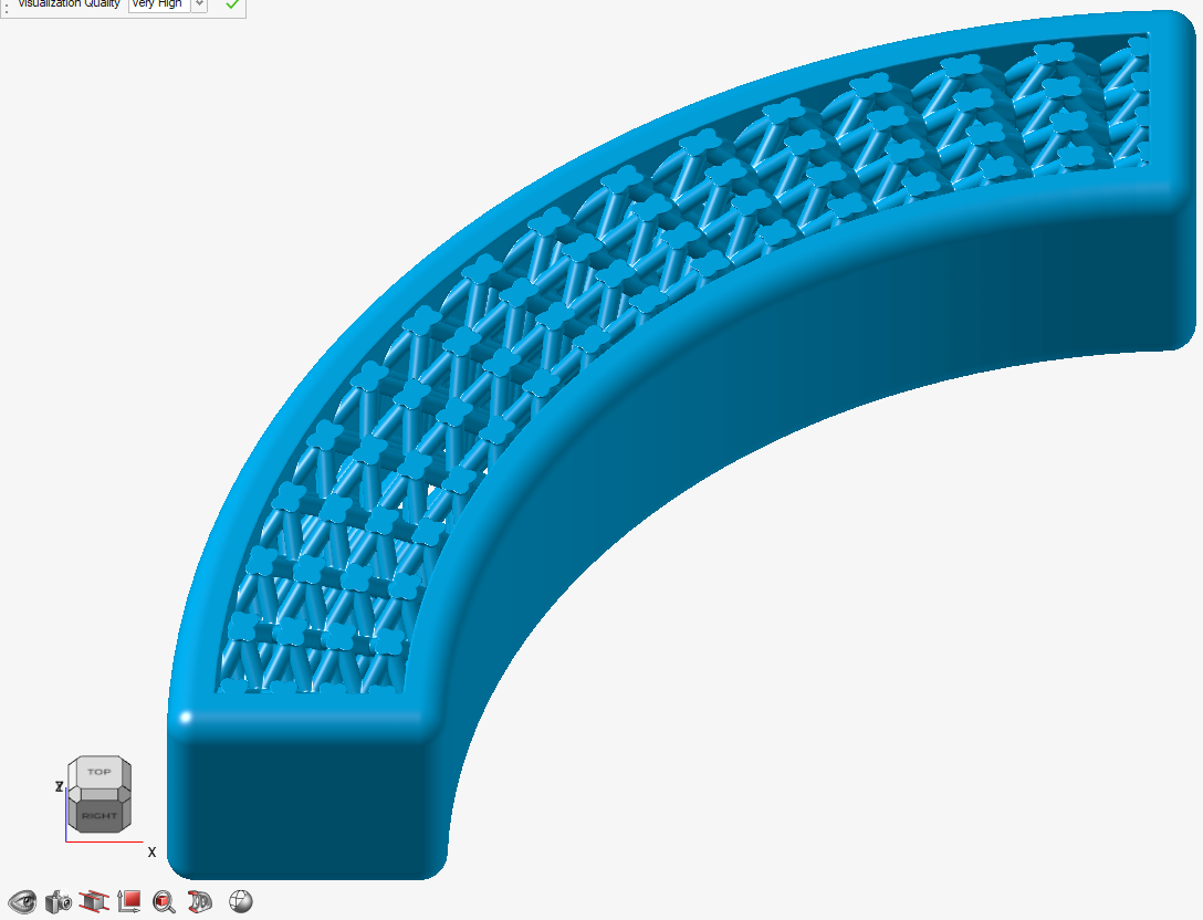
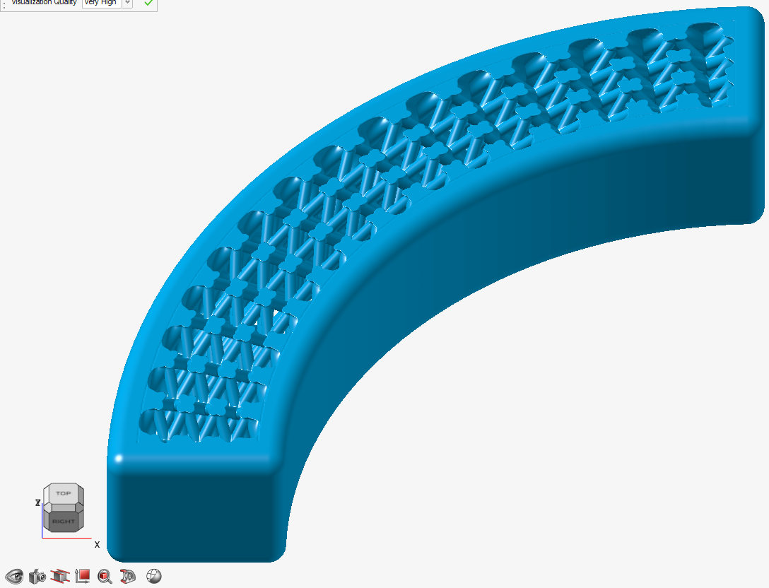
Cell - Fill Select between solid or hollow struts. - Solid: Create solid
struts.
- Hollow: Create hollow
struts.
Coordinate System - Type Select a type of coordinate system. All three coordinate systems have three directions. - Cartesian (x, y, z)
- Direction 1 is x, which is linear.
- Direction 2 is y, which is linear.
- Direction 3 is z, which is linear.
- All three directions are orthogonal to each other.
- Cylindrical (r, θ, z):
- Direction 1 is r (radius), which is measured radially from the z-axis.
- Direction 2 is θ, which is angular about the z-axis where θ = 0 aligns to the x-axis.
- Direction 3 is z, which is linear.
- Spherical (r, θ, φ):
- Direction 1 is r (radius), which is measured radially from the z-axis.
- Direction 2 is θ, which is angular and denotes azimuth (measured about the z-axis).
- Direction 3 is φ, which is angular and denotes elevation (measured relative to the XY plane).

Coordinate System - Origin Locate: Use the Move tool to position and orient the local coordinate system of the lattice. Coordinate System - Conform to Use this option to generalize a Cartesian lattice by creating conformal (curved) spaces that operate on the parametrized coordinates, U, V and W. You can select an existing Conformal Coordinate Space from the dropdown menu or create a new one. For more information, see Create a Conformal Coordinate Space. Coordinate System - Define Using the input fields for on-screen handles, define the minimum and maximum extents of each of the coordinate directions (Cartesian: x, y, z; Cylindrical: x, θ, z; Spherical: x, θ, φ). You can then specify the number of unit cells that will span these extents by sizing them according to Cell Count, or you can specify an Absolute unit cell size in length units.
When using Cell Count for unit cell sizing, you are guaranteed to have precisely the specified number of unit cells spanning the extents. If the count is an integer, the unit cells will begin and end perfectly on the boundaries of the extents (see the images below for an example in a spherical coordinate system)
In case of absolute sizing, unit cells are guaranteed to begin on the minimum extent of each coordinate direction but they are not guaranteed to terminate nicely on the upper extent of each direction.


Sizing - Strut Diameter All beams in the strut lattice have a circular cross-section. Enter the strut diameter. You can directly enter the diameter, controlled with a variable, or controlled in each position in space using a field (field-driven design). Sizing - Strut Inner Diameter (Hollow Only) Enter the inner diameter of the strut. Sizing - Type Choose between defining the lattice size by an absolute dimension or the number of cells. - Absolute: Enter an absolute length value, or an absolute angle value, for non-Cartesian coordinate systems, along each axis.
- Cell Count: Enter the number of cells along each axis.
Sizing - Uniform (Cartesian Only) Make the unit cell dimensions equal along the x- and y-axes. Sizing - Width Enter the cell size or count along the x-axis. Sizing - Height Enter the cell size or count along the y-axis. X (Cartesian Only) Enter the cell size or count along the x-axis. You can directly enter the cell size or count, controlled with a variable, or controlled in each position in space using a field (field-driven design). Y (Cartesian Only) Enter the cell size or count along the y-axis. You can directly enter the cell size or count, controlled with a variable, or controlled in each position in space using a field (field-driven design). Z (Cartesian and Cylindrical Only) Enter the cell size or count along the z-axis. You can directly enter the cell size or count, controlled with a variable, or controlled in each position in space using a field (field-driven design). θ (Cylindrical and Spherical Only) θ is angular about the z-axis where θ = 0 aligns to the x-axis. You can directly enter the cell size or count, controlled with a variable, or controlled in each position in space using a field (field-driven design). φ (Spherical Only) φ is angular and denotes elevation (measured relative to the XY plane). You can directly enter the cell size or count, controlled with a variable, or controlled in each position in space using a field (field-driven design). - Body-Centered Cubic
-
Select the Outer Body tab.
- Select a type of outer body.
- None: Don't create an outer body.
- Shell: Create an offset shell with an optional
trimming body.
Option Description Direction Select an offset direction for the shell. - Outward: Offset the shell outward from the lattice, increasing the size of the overall object.
- Inward: Offset the shell inward, consuming some of the lattice but maintaining the overall dimensions of the lattice.
- Both: Offset the shell both inward and outward.
Symmetry Symmetrically offset the shell inward and outward by the same distance. Outer Thickness Define the outward shell's offset thickness. You can directly enter thickness, controlled with a variable, or controlled in each position in space using a field (field-driven design). 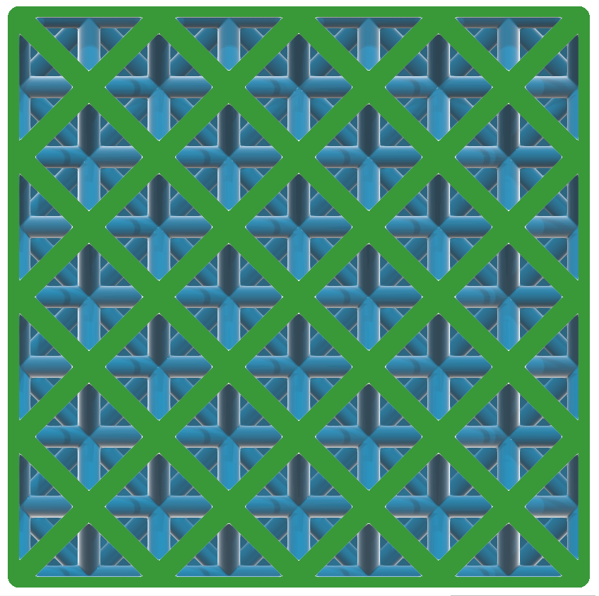
Inner Thickness Define the inward shell's offset thickness. You can directly enter thickness, controlled with a variable, or controlled in each position in space using a field (field-driven design). 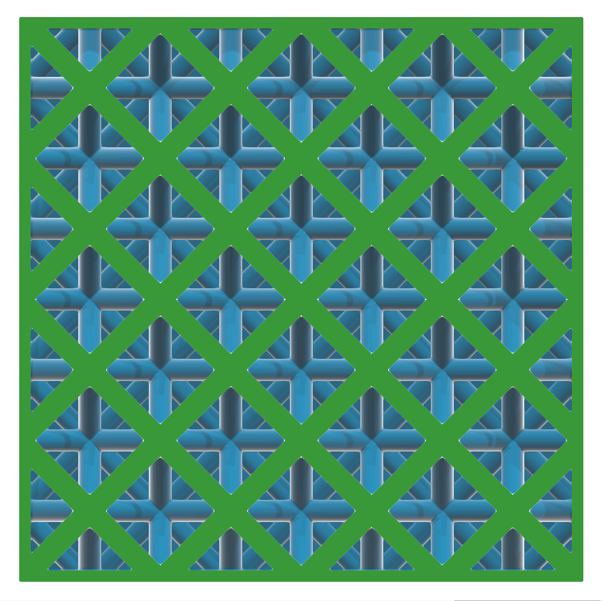
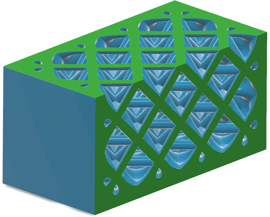
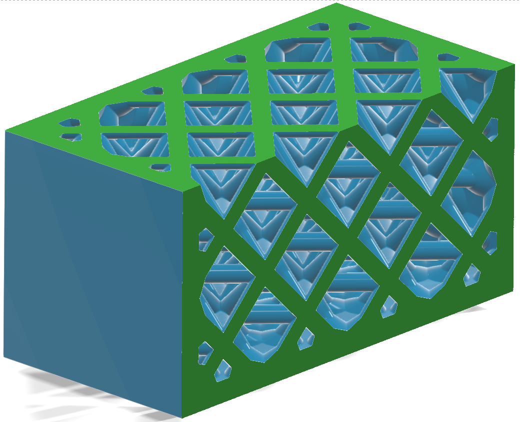
Trimming Body Select a body that's used to trim the shell. You can use this to trim areas of the shell, which is useful for fitting the lattice and its shell into a predefined volume, or when you want to expose some of the lattice so that it is not covered by a shell. In this example, a BRep body is chosen as the trimming body to expose some of the lattice. This image shows how the outward shell applied to the lattice overlaps with the trimming body.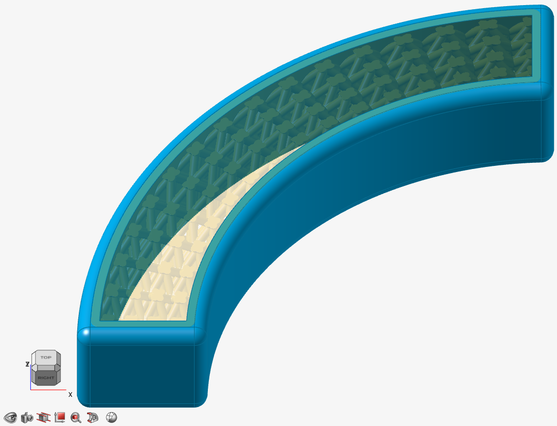 After the trimming is applied, some of the outward shell is cut away, exposing the lattice wherever the shell protrudes beyond the confines of the trimming body.
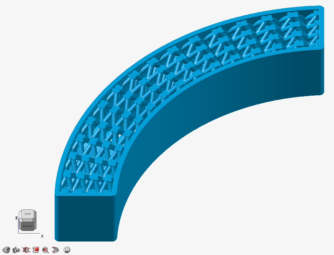
Transition Choose the type of transition between the outer body and lattice body. - Sharp: The lattice abruptly joins the surrounding shell.
- Fillet: The lattice
blends into the surrounding shell using a fillet.
If you
select this option, define the fillet
Radius.
- Chamfer: The lattice
blends into the surrounding shell using a chamfer.
If you select this option, define the chamfer
Distance. For Fillet, the
distance is the radius of the fillet and, for
Chamfer, the distance is the setback of the
chamfer. You can directly enter the distance,
controlled with a variable, or controlled in each
position in space using a field (field-driven design).
- Combine: Combine the outer body with the lattice
body, directly, without creating a shell that surrounds the
lattice
Option Description Combine Body Select a body to combine the planar lattice with. This body should be close to, or overlap with, the lattice. 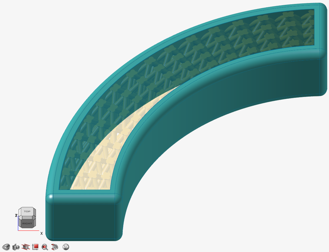
Transition Choose the type of transition between the outer body and lattice body. - Sharp: The lattice
abruptly joins the surrounding outer body.
- Fillet: The lattice
blends into the outer body using a fillet. If you
select this option, define the fillet
Radius.
- Chamfer: The lattice
blends into the outer body using a chamfer. If you
select this option, define the chamfer
Distance.

For Fillet, the distance is the radius of the fillet and, for Chamfer, the distance is the setback of the chamfer. You can directly enter the distance, controlled with a variable, or controlled in each position in space using a field (field-driven design).
- Sharp: The lattice
abruptly joins the surrounding outer body.
- Click OK.