
Create an Implicit Planar Lattice
Fill an implicit body with a planar lattice, which is a 2.5D cellular structure with a clearly defined 2D cross-section that is drawn or extruded along the third dimension.
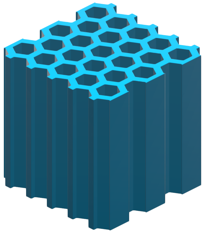
A popular example is a honeycomb structure.
-
On the Implicit Modeling ribbon, select the
Planar Lattice tool.

Tip: To find and open a tool, press Ctrl+F. For more information, see Find and Search for Tools. - Optional: For Visualization Quality, select from Low to Very High quality, which corresponds to a low to very high density of elements. A higher quality produces sharper geometry features but is more computationally intensive. When creating a complicated function, it’s recommended to work using a lower quality and then switch to a higher quality after the function is complete.
- Select one or more bodies to fill with planar lattice. You can select a Parasolid, STL, PolyNURBS, or implicit geometry.
-
In the guide panel, select the Lattice Body tab.
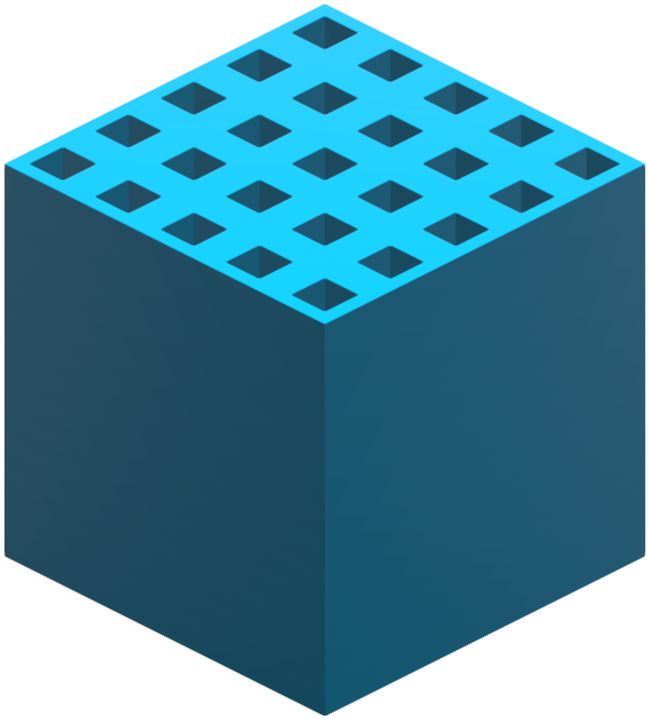
Option Description Cell - Type Select a cell type. - Hexagon
- Diamond
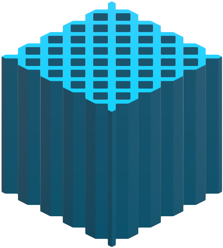
- Rectangle
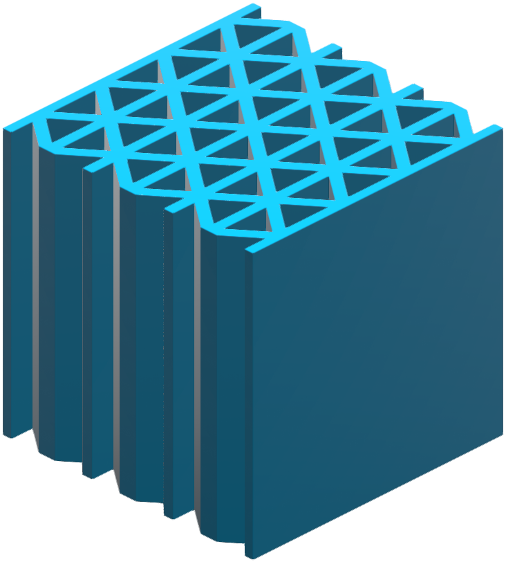
- Triangle
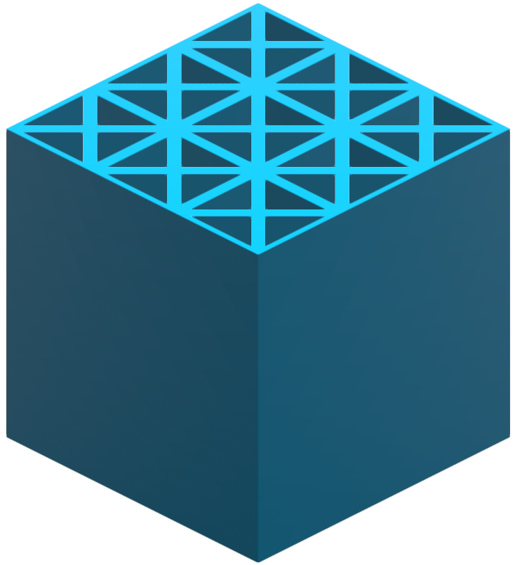
- Isogrid
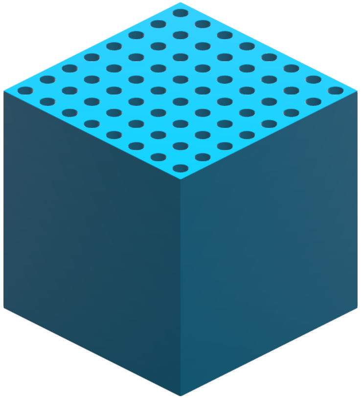
- Circle
- Custom Unit Cell
Selecting this option will open the Unit Cell editor to start creating a new planar lattice unit cell. For more information, see Create a Custom Planar Unit Cell.
Cell - Solid Region - Regular: Keep the solid and void domains of the lattice as-is.
- Inverted: Flip the solid and void domains of the lattice.
Coordinate System - Type Select a type of coordinate system. All three coordinate systems have three directions. - Cartesian (x, y, z)
- Direction 1 is x, which is linear.
- Direction 2 is y, which is linear.
- Direction 3 is z, which is linear.
- All three directions are orthogonal to each other.
- Cylindrical (r, θ, z):
- Direction 1 is r (radius), which is measured radially from the z-axis.
- Direction 2 is θ, which is angular about the z-axis where θ = 0 aligns to the x-axis.
- Direction 3 is z, which is linear.
- Spherical (r, θ, φ):
- Direction 1 is r (radius), which is measured radially from the z-axis.
- Direction 2 is θ, which is angular and denotes azimuth (measured about the z-axis).
- Direction 3 is φ, which is angular and denotes elevation (measured relative to the XY plane).

Coordinate System - Origin Locate: Use the Move tool to position and orient the local coordinate system of the lattice. Coordinate System - Conform to Conform to: use this option to generalize a Cartesian lattice by creating conformal (curved) spaces that operate on the parametrized coordinates, U, V and W. You can select an existing Conformal Coordinate Space from the dropdown menu or create a new one. For more information, see Create a Conformal Coordinate Space. 
Sizing - Thickness Enter the thickness of the lattice wall. You can directly enter the thickness, controlled with a variable, or controlled in each position in space using a field (field-driven design). Sizing - Type Choose between defining the lattice size by an absolute dimension or the number of cells. - Absolute: Enter an absolute length value, or an absolute angle value for non-Cartesian coordinate systems, along each axis.
- Cell Count: Enter the number of cells along each axis that will fill the bounding volume of the body.
Sizing - Uniform (Cartesian Only) Make the unit cell dimensions equal along the x- and y-axes. Sizing - Width Enter the cell size or count along the x-axis. You can directly enter the cell size, controlled with a variable, or controlled in each position in space using a field (field-driven design). Sizing - Height Enter the cell size or count along the y-axis. You can directly enter the cell size, controlled with a variable, or controlled in each position in space using a field (field-driven design). Plane - Vector To control the direction in which the planar lattice is extruded, choose a predefined vector or enter the x, y, z components.- X Vector: Extrude the planar lattice along the local x-axis by setting the vector to [1, 0, 0].
- Y Vector: Extrude the planar lattice along the local y-axis by setting the vector to [0, 1, 0].
- Z Vector: Extrude the planar lattice along the local z-axis by setting the vector to [0, 0, 1].
- X Component: Enter the x component of the vector.
- Y Component: Enter the y component of the vector.
- Z Component: Enter the z component of the vector.
- Hexagon
-
Select the Outer Body tab.
- Select a type of outer body.
- None: Don't create an outer body.
- Shell: Create an offset shell with an optional
trimming body.
Option Description Direction Select an offset direction for the shell. - Outward: Offset the shell outward from the lattice, increasing the size of the overall object.
- Inward: Offset the shell inward, consuming some of the lattice but maintaining the overall dimensions of the lattice.
- Both: Offset the shell both inward and outward.
Symmetry Symmetrically offset the shell inward and outward by the same distance. Outer Thickness Define the outward shell's offset thickness. You can directly enter thickness, controlled with a variable, or controlled in each position in space using a field (field-driven design). Inner Thickness Define the inward shell's offset thickness. You can directly enter thickness, controlled with a variable, or controlled in each position in space using a field (field-driven design). Trimming Body Select a body that's used to trim the shell. This can be used to trim areas of the shell, which is useful for fitting the lattice and its shell into a predefined volume, or when you want to expose some of the lattice so that it is not covered by a shell. Transition Choose the type of transition between the outer body and lattice body. - Sharp: The lattice abruptly joins the surrounding shell.
- Fillet: The lattice blends into the surrounding shell using a fillet. If you select this option, define the fillet Radius.
- Chamfer: The lattice blends into the surrounding shell using a chamfer. If you select this option, define the chamfer Distance. For Fillet, the distance is the radius of the fillet and, for Chamfer, the distance is the setback of the chamfer. You can directly enter the distance, controlled with a variable, or controlled in each position in space using a field (field-driven design).
- Combine: Combine the outer body with the lattice
body, directly, without creating a shell that surrounds the
lattice.
Option Description Combine Body Select a body to combine the planar lattice with. This body should be close to, or overlap with, the lattice. Transition Choose the type of transition between the outer body and lattice body. - Sharp: The lattice abruptly joins the surrounding outer body.
- Fillet: The lattice blends into the outer body using a fillet. If you select this option, define the fillet Radius.
- Chamfer: The lattice blends into the outer body using a chamfer. If you select this option, define the chamfer Distance. For Fillet, the distance is the radius of the fillet and, for Chamfer, the distance is the setback of the chamfer. You can directly enter the distance, controlled with a variable, or controlled in each position in space using a field (field-driven design).
- Click OK.