Visualization Quality and Mesh Settings for Implicit Modeling
Learn how to use the Visualization Quality and Meshing Settings to manage compute times, the visual appearance, and the geometric accuracy of implicit and mesh geometry when working with Inspire Implicit Modeling. This includes working in Implicit Modeling, converting other geometry formats in Implicit Modeling, and meshing implicit geometry for export or other downstream processes.
Introduction to Visualization Quality
Advice for Managing the Visualization Quality
A good habit to form is to change the Visualization Quality to suit what you are doing at any given time. For example, computationally intensive operations, such as using Convert in Implicit Modeling, might be best attempted at a lower Visualization Quality first, then increasing the quality when you are satisfied that the operation is running correctly. Conversely, when creating models for export or render, it is recommended to try and use the highest feasible Visualization Quality for your computer.
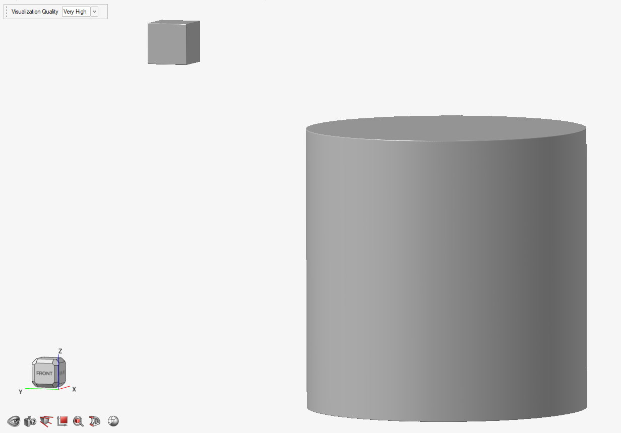
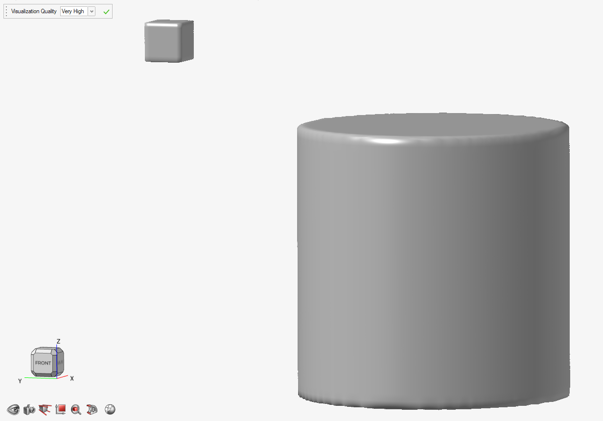
If we use a Boolean Combine operation to join these two objects, they will be treated as a single entity. This means they will each be captured in the same voxel grid. Because many of the voxels are now being used to model the empty space between the two objects, there are fewer voxels dedicated to modeling each shape. In the image below, you can see the clear reduction in geometric accuracy, where edges that were previously sharp are now rounded. This is despite the fact that the Visualization Quality is the same in both images. You should keep this in mind when combining objects that are physically separated by a large distance.
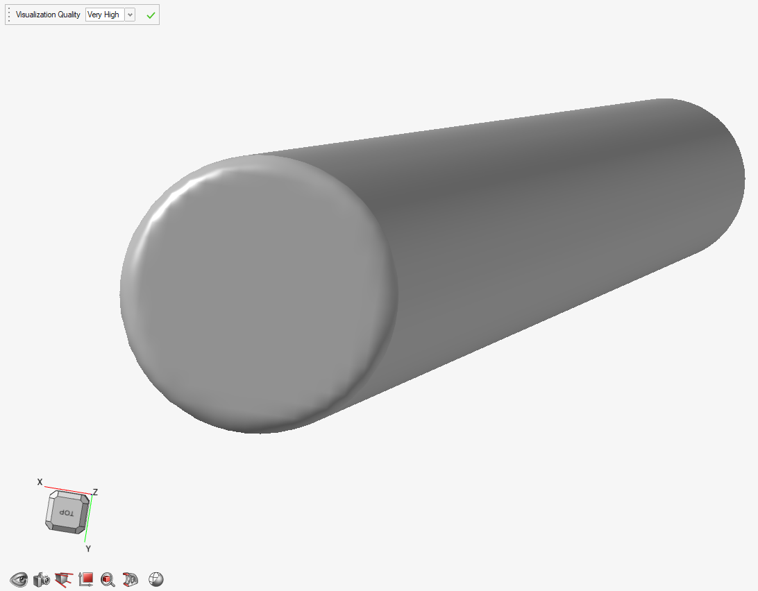
The final piece of advice is to consider the alignment of the geometry within the voxel grid. In every case, the voxel grid is aligned to the global x-, y-, and z-directions. We call this an axis-aligned grid. Also, the voxels in the grid are always cubic elements. Features with curvature will be captured more or less accurately depending on how they cut through the voxels. As an illustrative thought exercise, imagine trying to represent a 2D straight line using a digital image with pixels. If the line is horizontal or vertical within the image, the representation will be sharp and accurate. However, if the line is diagonal in the image, you can expect to see a staircase-like effect along the lines as the it passes through pixels in different rows and columns.
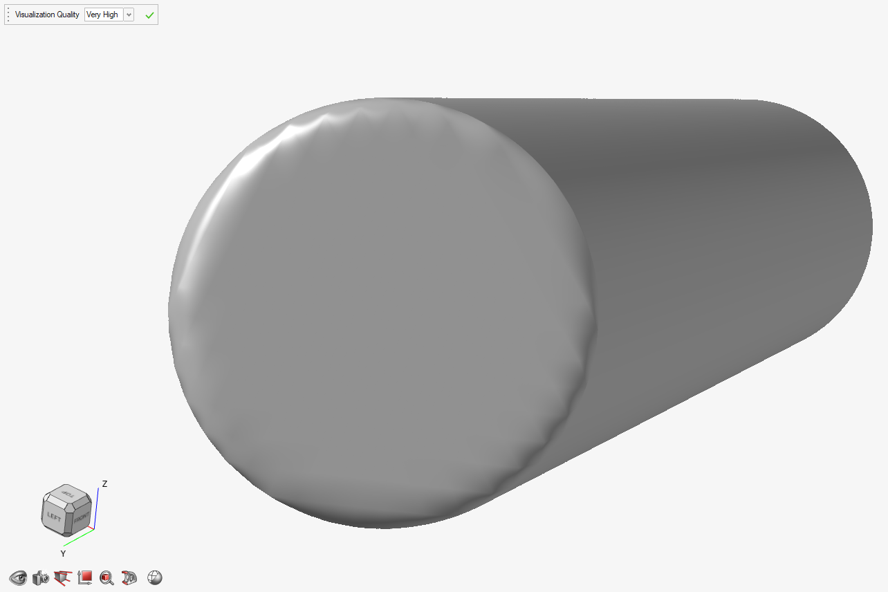
There is a further loss of accuracy if we align the cylinder along the body diagonal of the axis-aligned bounding box (from, say, the bottom-front-left to the top-rear-right corner). In the image below, we can see further loss of accuracy as a result of the aforementioned staircase effect where the features of the cylinder do not align favorably with the discrete voxel grid. Although this is an inherent property of modeling this way, being aware of this effect can help you to effectively minimize its impact.
Converting Implicit Models to Triangle Meshes
- The software responsible for build preparation on your additive manufacturing machine (3D printer) accepts or prefers triangle mesh formats.
- You have critical geometrical features that need to be preserved, such as sharp edges, but you also want to incorporate implicit geometry in the design, so you convert everything into a triangle mesh format prior to the Combine operation.
- You are working on a model that will subsequently be sent to analysis (e.g., a structural simulation), and the simulation pipeline cannot interpret Implicit Modeling geometry.
- You want to use geometry editing tools that do not accept implicit models as an input (e.g., Sculpt in PolyMesh).
- You wish to send your design to a colleague or customer who does not have access to Inspire Implicit Modeling.
The following steps walk you through the process of converting an implicit part into a triangle mesh, making the most of the Implicit Meshing options to suit your application.
- Complete your edits of the implicit part by clicking the green check
mark.
- Ensure the Property Editor window is visible by selecting the option under the View tab.
- Select the implicit part that you wish to convert to a triangle mesh, either by selecting it in the Model Browser or by clicking the model in the scene.
- Scroll to the bottom of the properties in the Property Editor window to find
the Implicit Meshing properties.
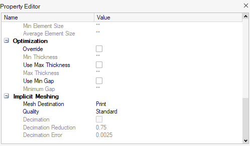
- Select the destination for your mesh. For simulation, select the Analysis option. For export for printing or saving the file, select Print.
- Choose your quality settings from the two options: Standard or Custom.
- Right-click the model you wish to convert (either in the Model Browser or directly on the model in the scene), and then select Convert to Triangle Mesh.
- Choose a conversion setting in the Convert to Triangle Mesh dialog.
Option Description Create sharp edges and specify mesh size Sharp edges are created at the boundaries based on the geometry of the original implicit part. Type a value in the Average mesh size box to set the size of the triangle mesh. A higher average mesh size generates fewer triangles and vice versa. Specify mesh size Type a value in the Average mesh size box to set the size of the triangle mesh. The original surface geometry is not preserved. A higher average mesh size generates fewer triangles and vice versa. Use implicit visualization quality Triangle mesh is created as visualized. Higher implicit visualization quality generates more triangles and vice versa. - Click Convert.
Guidance for Choosing Implicit Meshing Properties
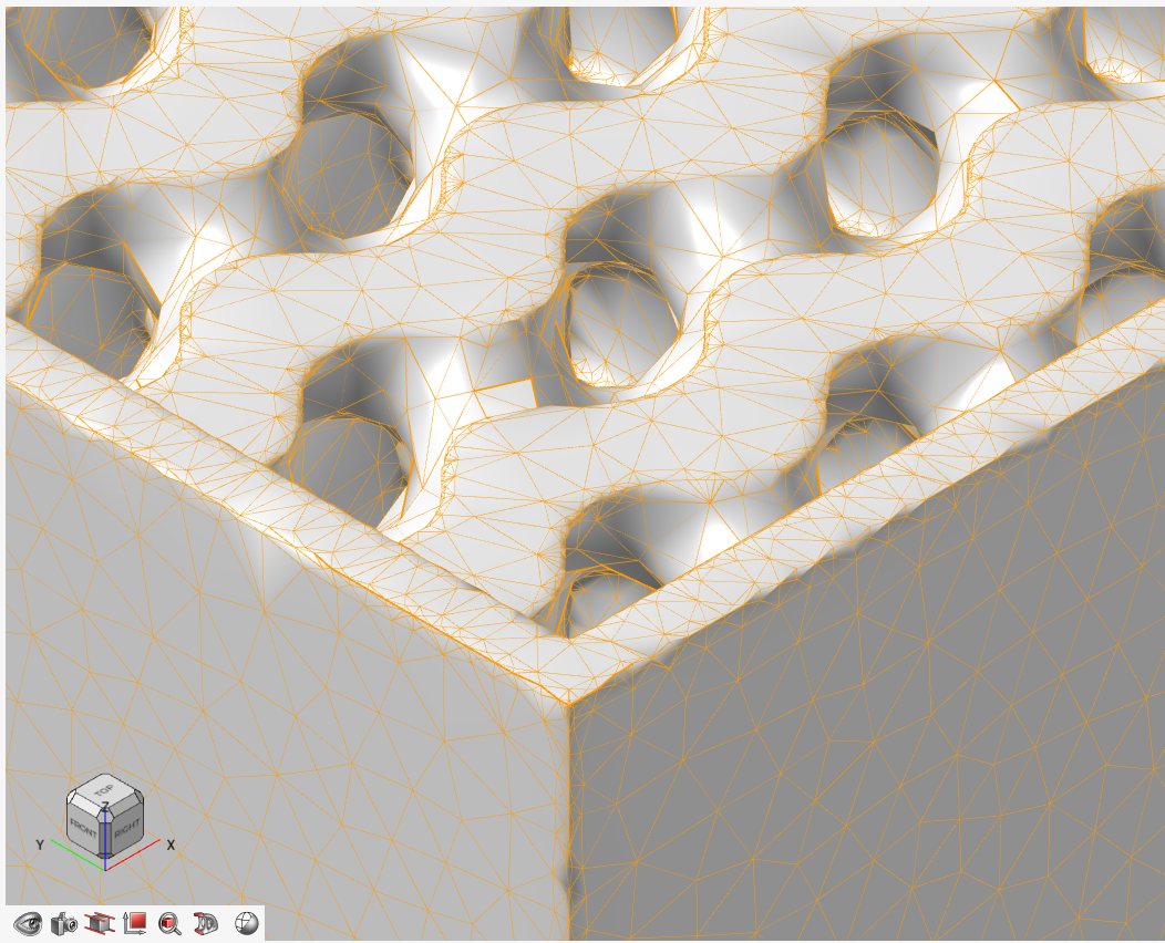
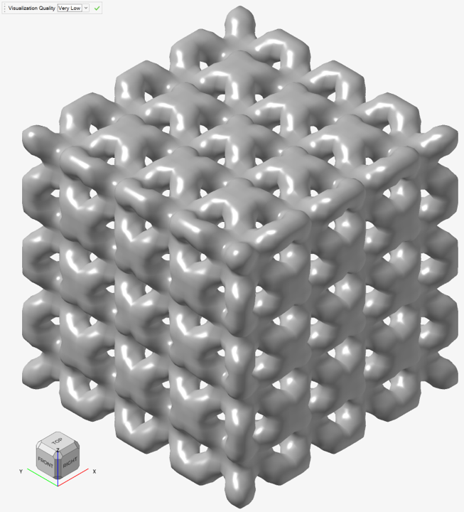
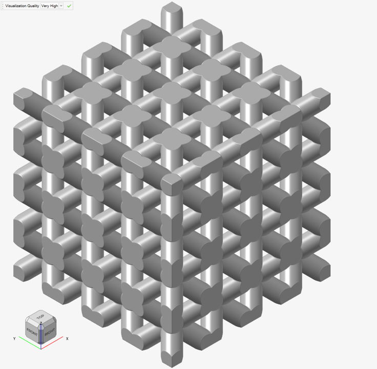
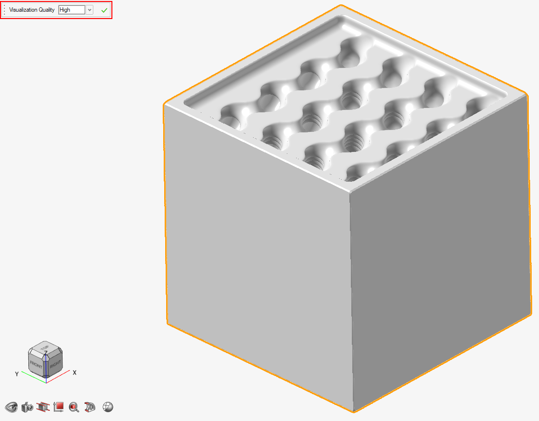
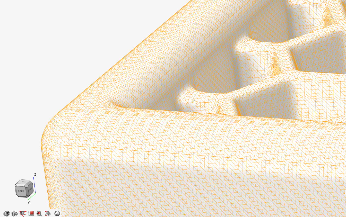
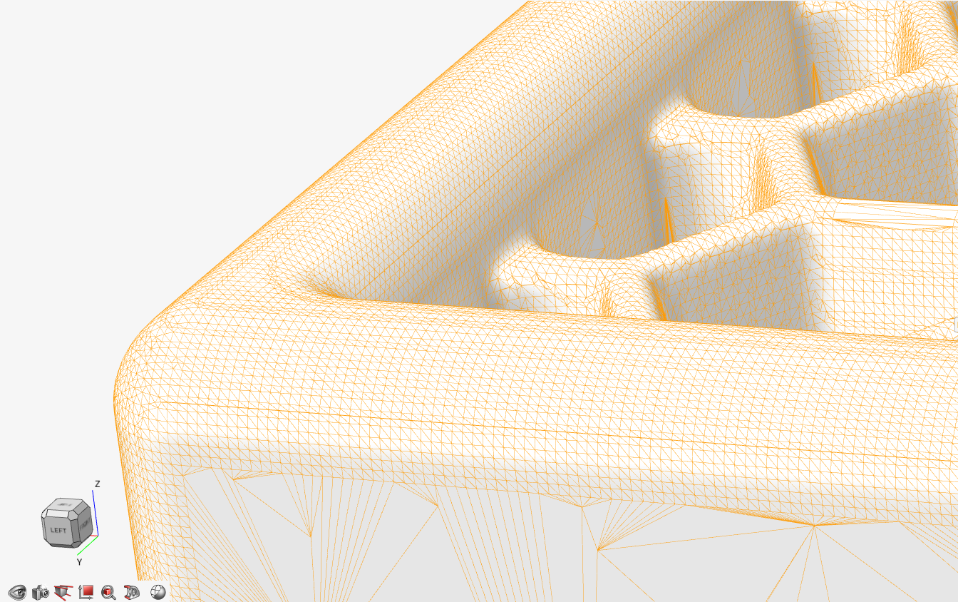
Firstly, you should note that the quality of the mesh that is produced in the conversion relates directly to the Visualization Quality setting that was used during Implicit Modeling. If the Very High setting was used, the triangle mesh will be very fine, as shown in the image below. Using progressively lower Visualization Quality settings will produce increasingly coarse meshes.
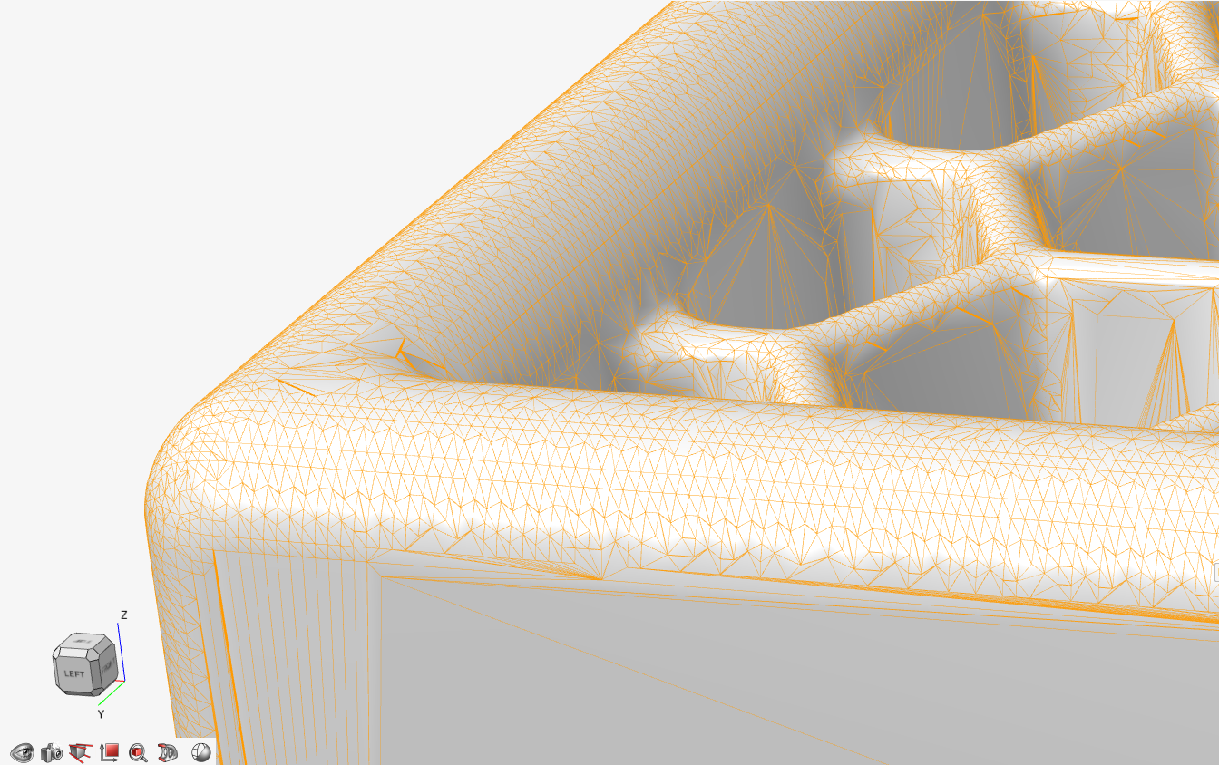
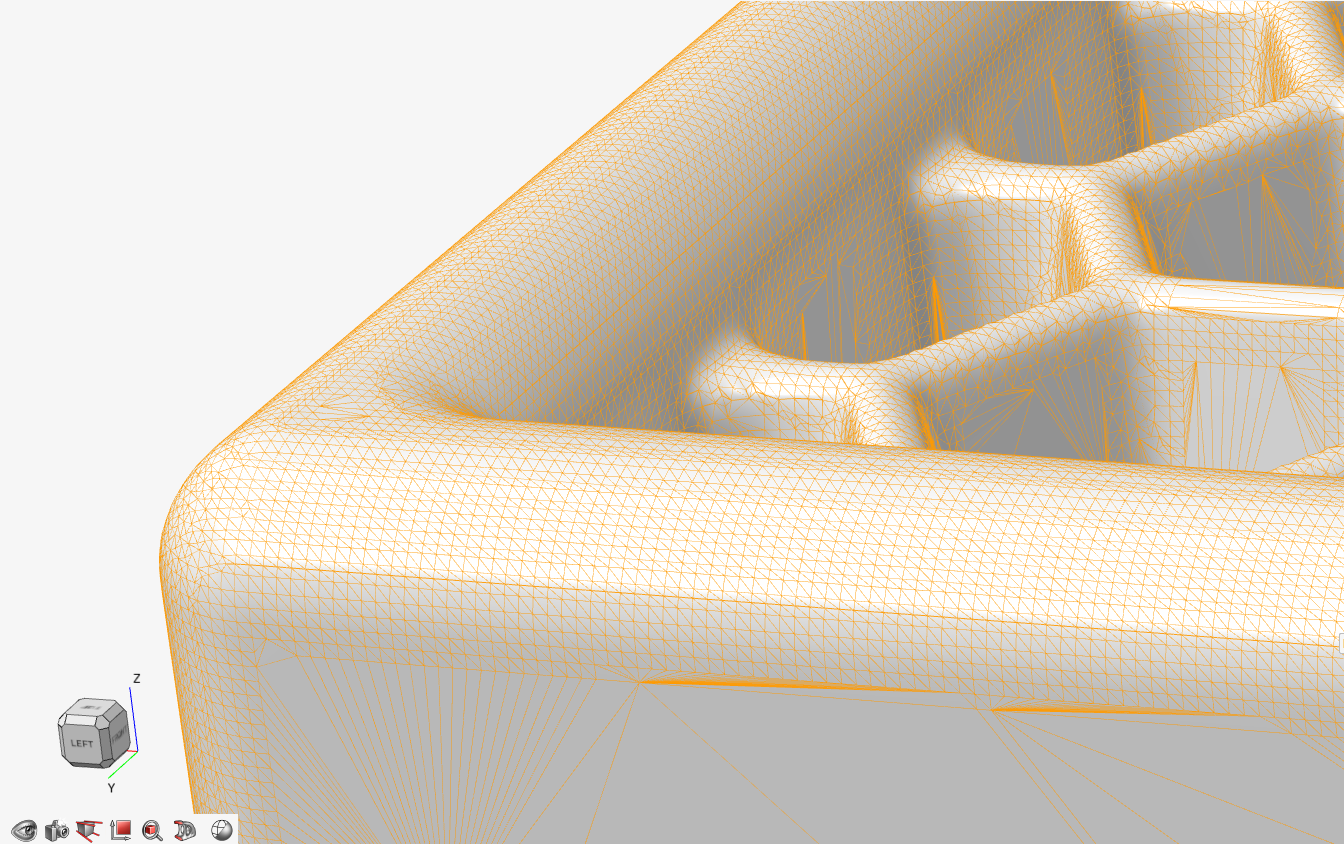
If the decimation using the default settings is too aggressive, you can reduce the Decimation Reduction property. The Decimation Reduction property should be a number between zero and one. Setting the reduction to, say, 0.9 is the same as asking for a 90% reduction in the total triangle count in the mesh (compared to the original mesh). Conversely, 0.4 is the same as asking for a 40% reduction. The image above uses 0.75 and the image below uses 0.4. You can see that there are more triangles in the image below, and the mesh is a better approximation of the original fine mesh.
The Decimation Error property is a value specified as a percentage of the bounding box size. This specifies the permissible deviation between the original fine mesh and the newly decimated mesh. Setting this property to smaller values generate meshes that reproduce the geometry in the original fine mesh more accurately. As a limit case, this value can be set to zero, which typically means that triangles are only merged if the region is planar and there is no loss of accuracy. The impact of doing this is shown below.
Meshes for Analysis
If the destination for your mesh is analysis, such as a structural simulation, neither the original fine mesh nor the decimated mesh will be appropriate. The fine mesh is almost certainly too fine and will unnecessarily slow the analysis pipeline down. Conversely, decimated meshes contain triangles that are generally too large, covering large expanses with a single triangle.