
Convert to Implicit Geometry
Convert parts, surfaces, and curves to implicit objects. You can select CAD, PolyNURBS, meshes, or optimized parts, surfaces, or curves.
The output is a Signed Distance Field (SDF) for
the converted geometry, with negative scalar values inside the object and positive
scalar values outside the object (the surface exists at positions with scalar values
of zero).
Note: Converting nonsolid objects will technically
produce an Unsigned Distance Field (UDF) since there is no interior volume that
will have negative field values. Offsetting these fields outward will produce a
SDF as it will create a solid volume around the surface(s) or
curve(s).
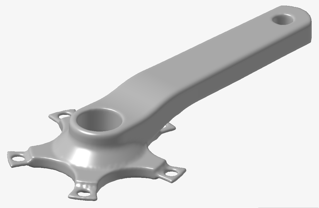
The process begins with a BRep (NURBS), subdivision, or tessellated surface mesh
(e.g. STL) geometry such as the BRep crank model shown below.

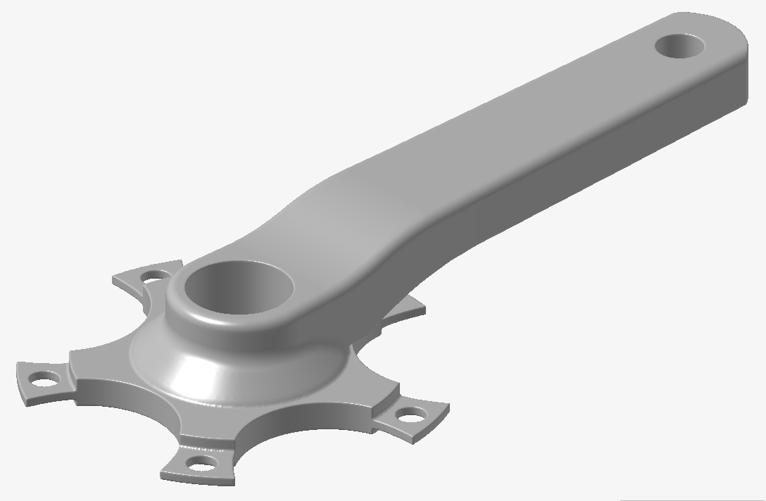
Based on the Visualization Quality setting that is
active in the Implicit Modeling ribbon, the converted object will be less or more
accurate and sharp. The next image shows the result of the conversion using the
Medium Visualization Quality setting. This model will compute very quickly, but note
the rounded edges and loss of sharp features in general.
To produce a more accurate Implicit reproduction of the original BRep model, the following image was created using the Very High Visualization Quality setting. Note the marked improvement in the sharpness of features, such as edges. This quality comes at the cost of a longer compute time, and a general increase in memory allocation to manipulate this object. It is recommended that you select a Visualization Quality that balances the trade-off between visual quality and compute time on their machine. You can always design at a lower Visualization quality and then increase this value periodically to check the appearance at higher quality settings.
To produce a more accurate Implicit reproduction of the original BRep model, the following image was created using the Very High Visualization Quality setting. Note the marked improvement in the sharpness of features, such as edges. This quality comes at the cost of a longer compute time, and a general increase in memory allocation to manipulate this object. It is recommended that you select a Visualization Quality that balances the trade-off between visual quality and compute time on their machine. You can always design at a lower Visualization quality and then increase this value periodically to check the appearance at higher quality settings.
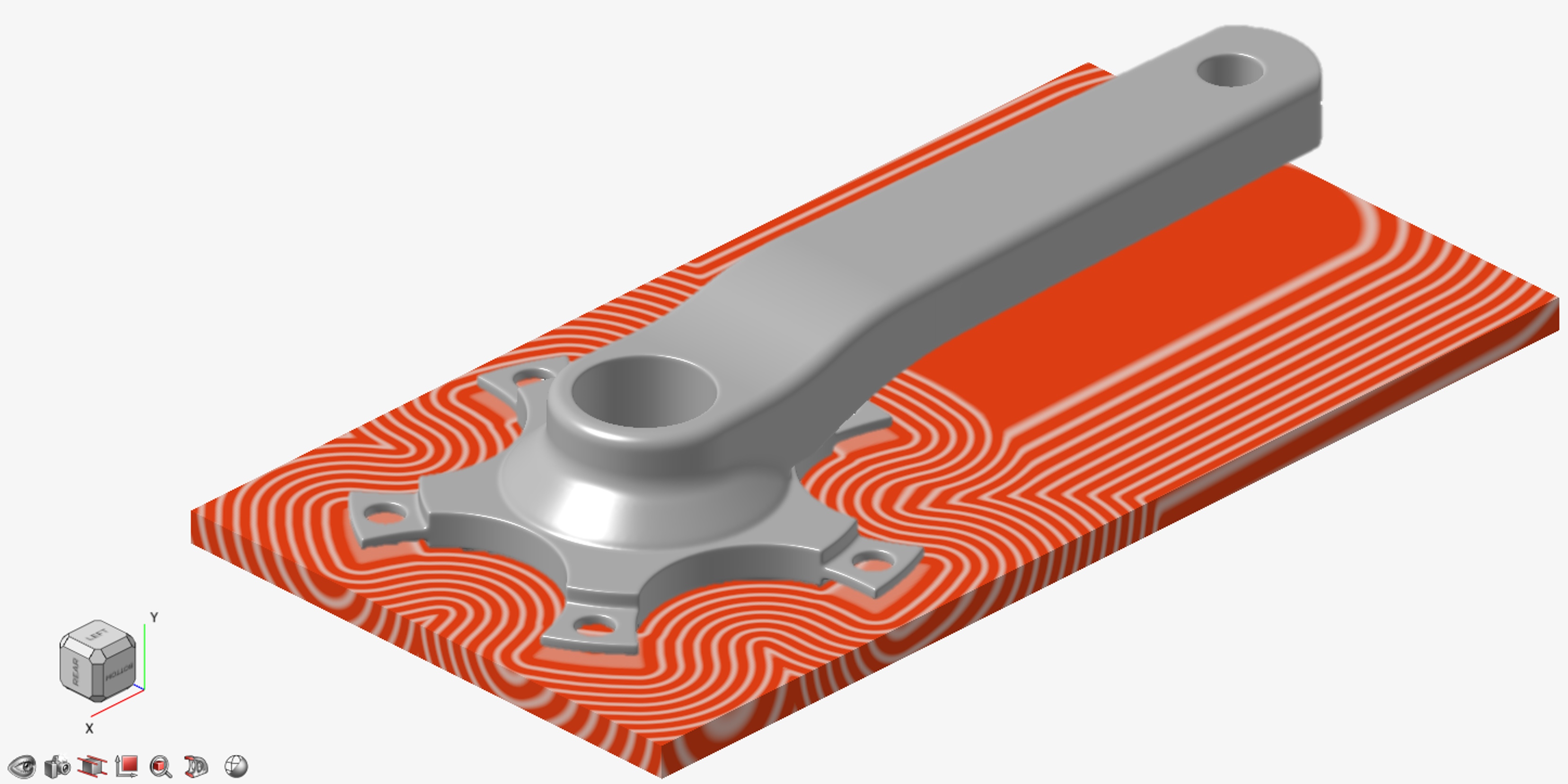
This final image shows the converted implicit model
overlaid on a sectioned view of its Signed Distance Field (SDF).
Note: For a much more detailed discussion around handling
quality when converting into and out of Implicit Modeling, please see Visualization Quality and Mesh Settings for Implicit Modeling.
-
On the Implicit Modeling ribbon, select the
Convert tool.

Tip: To find and open a tool, press Ctrl+F. For more information, see Find and Search for Tools. -
On the Convert to Implicit guide panel, select the
appropriate tab for the type of object(s) required for the conversion.

- Parts: Allows selection of multiple nonimplicit parts. Each selected part will be converted to an implicit version of the part.
- Surfaces: Will convert all selected objects to a
single implicit collection of surfaces. Use the
 to change between selecting parts or individual
surfaces. This will produce an implicit set of surfaces that will have zero
volume and hence be an unsigned distance field (no negative
values).
to change between selecting parts or individual
surfaces. This will produce an implicit set of surfaces that will have zero
volume and hence be an unsigned distance field (no negative
values). - Curves: Will convert all selected objects to a
single implicit collection of curves. Use the to change between selecting parts, surfaces or
individual curves. Curves will be extracted from all selected parts or
surfaces. This will produce an implicit set of curves which will have zero
volume and hence be an unsigned distance field (no negative
values).
- Optional: For Visualization Quality, select from Low to Very High quality, which corresponds to a low to very high density of elements. A higher quality produces sharper geometry features but is more computationally intensive. When creating a complicated function, it’s recommended to work using a lower quality and then switch to a higher quality after the function is complete.
-
Select one or more parts, surfaces, or curves to convert to implicit bodies. A
new implicit object will be created for each converted part; multiple surfaces
or curves will be converted into a single implicit object.
Note: Convertible formats include BRep (e.g., Parasolid, STEP, etc.), PolyNURBS (subdivision surfaces), and polymesh (tessellated surface meshes including .stl, .obj, .3mf, etc.). It is also possible to convert the geometry results arising from simulation and optimization workflows, such as topology optimization results.
- Click OK.