
Conformal Coordinate Spaces
Construct a conformal coordinate space to make body-fitted implicit patterns and lattices.
Use lines, curves, and surfaces to construct a coordinate space that conforms to the defined geometry. This can be used with Implicit Pattern and Lattice tools to make them body-fitted instead of being aligned to conventional coordinate directions (Cartesian, Cylindrical, and Spherical). For more information, see Create a Conformal Pattern and Create a Conformal Lattice.
Conformal coordinate spaces can be 1-, 2- or 3-dimensional and are defined by a set of features defining the U, V and W directions of the parametrization. There are a number of options for defining the 2- and 3-dimensional parametrizations; these can be seen on the Conform guide panel.

- 1D conformal coordinate spaces can only be created based off a single curve. The
Invert U parameter allows for the 0-1 parametrization
for the curve to be inverted.

- 2D conformal coordinate spaces can be created either from a single surface or
two curves to create a virtual surface. For both types, the U and V parameters
can be inverted, and for the single-surface mode, the U and V parameters can be
swapped so the U definition of the surface becomes the V and vice versa.
Figure 1. Conforming a single surface 
Figure 2. Conforming two curves 
- 3D conformal coordinate spaces can be created from two surfaces, which creates a
lofted conformal volume between them, a surface and a curve, which creates a
swept conformal volume or a virtual volume defined with three separate
curves.
Figure 3. A conformal grid from two surfaces 
Figure 4. A conformal grid from a surface and a curve 
Figure 5. A conformal grid from three curves 
Create a Conformal Lattice
Make body-fitted implicit lattices.
Lattices created using Implicit Modeling have the option to conform to a user-selected parametric (BRep) surface.
-
Starting from a BRep geometry, select the model you want to lattice and click
the Surface Lattice tool on the Implicit Modeling
ribbon.


-
In the Surface Lattice guide panel, click the Conform to
dropdown and select Create Conformal.

-
Use the Conform guide panel to adjust conform settings.
- Single surface: uses surface UVs and the surface normal as the W
directionIn the Conform guide panel, select the Surface tab, ensure the Type is set to Surface, click Select and then click the surface you want to conform in the model. You will have the option to reverse the direction of the U and V coordinate parametrizations and also which coordinate directions are used as U and V.

- Two surfaces: interpolates the UVs of each surface with the W going
between both surfaces
In the Conform guide panel, select the Volume tab, ensure Type is set to Two Surfaces, and use the From Surface and To Surface collectors to pick which surfaces to use to create the conformal volume. You will have the option to reverse the direction of the U and V coordinate parametrizations for and flip which coordinate directions are used as U and V for each surface. This is useful if the two surfaces are not defined in the same directions and avoids twisting in the conformal domain.

- Single surface: uses surface UVs and the surface normal as the W
direction
-
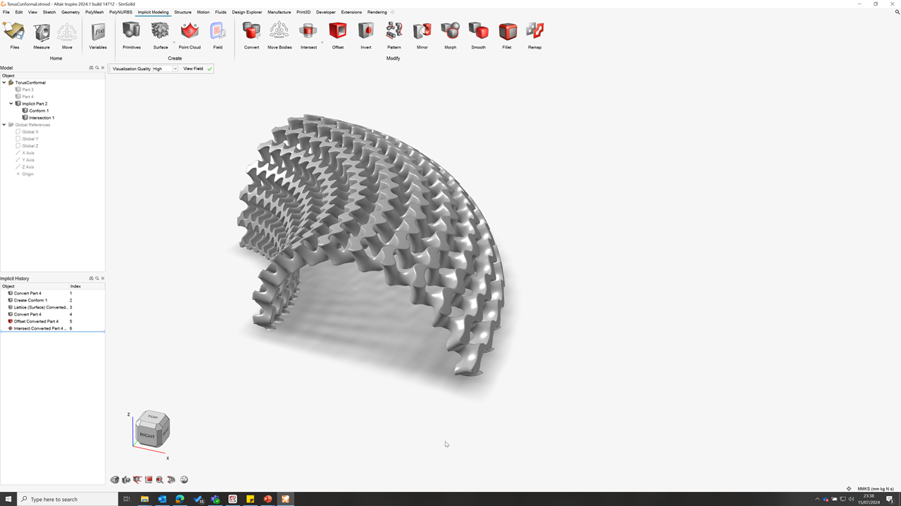
The end result is a lattice that follows the parametric coordinate
directions of the surface, which makes it possible to terminate each unit cell
nicely on the boundary of the original body. For clarity, the parametrized
coordinate direction W is always perpendicular to the selected surface. The
following images depict a conformal lattice from a single surface or between two
surfaces.
Create a Conformal Pattern
Construct a conformal coordinate space to make body-fitted implicit patterns.
- Construct the geometry from which the conformal coordinate space will be constructed (lines, curves, and BRep surfaces).
- Construct the implicit body that will be patterned across the conformal coordinate space.
- Create or select the conformal coordinate space from within the Pattern context.
- Make any edits to U, V , and W parametric coordinate directions, such as reversing their direction or flipping which direction is denoted as U or V.
- Select the Base Point for the pattern for each parametric coordinate direction that is used (U, V and W, as required). The Base Point is a point on each parametric coordinate direction that the original instance of the geometry takes as its starting point for the pattern.
- Specify pattern Spacing and Count in each direction according to your requirements. Spacing can be given in either length units or parametrized distance.
The following sections give examples of some of the different Conformal Pattern options.
-
1D Pattern Along Curve
Implicit bodies can be patterned along a single curve. Instances of the selected implicit body will follow the curve and can be spaced evenly in terms of parametric coordinates or according to a distance in length units.

-
2D Pattern Along Two Curves
Implicit bodies can be patterned along two curves. Instances of the selected implicit body will follow the surface implied by the two curves and can be spaced evenly in terms of parametric coordinates or according to a distance in length units.

-
2D Pattern Between Two Curves
Implicit bodies can be patterned on a surface created by lofting between two curves. A number of interpolated curves will be created between the two selected curves based on the selected V spacing.
-
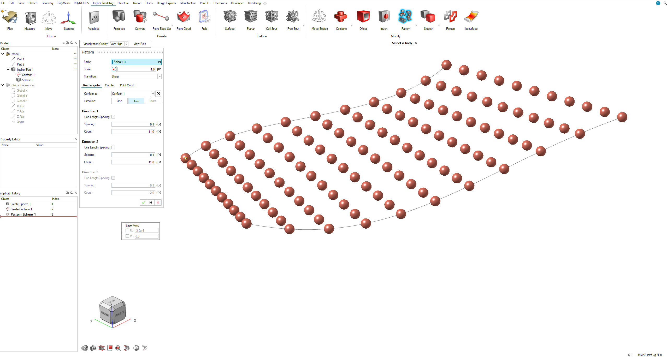
2D Pattern Across Parametric Surface (BRep)
When conforming to a surface, you can specify the spacing of the pattern so instances are evenly spaced in parametric U- and V-coordinates or spaced according to some distance in length units. Often, the most intuitive results come from even spacing in U and V.

-
3D Pattern Between Two Surfaces
A virtual volume can be defined when creating a conformal coordinate space between two surfaces.

-
3D Pattern Along Three Curves
A virtual volume can be defined when creating a conformal coordinate space from three curves. Each curve will be used to define the parametrization of the U, V and W directions of the virtual volume.

-
3D Pattern Across Surface and Along a Curve
A virtual volume can be defined when creating a conformal coordinate space from a surface and a curve. The surface is used to define the U and V parametrization and the curve is used to define the W parametrization of the virtual volume.
