
Create Implicit Surface Perforations
Generate a set of struts to cut holes in an implicit body or join them to the body to create pins.

-
On the Geometry ribbon, select the Extract tool.

Note: The tool may be hidden in the dropdown menu. To access the dropdown menu, you can do one of the following:- Select
 at the lower
right corner of the currently displayed tool.
at the lower
right corner of the currently displayed tool. - Click and hold the currently displayed tool.
Tip: To find and open a tool, press Ctrl+F. For more information, see Find and Search for Tools.Note: The Extract tool will to create a new part from the selected surface(s) that will be used to generate points. You can skip steps 1 and 2 to use an entire part in this workflow, which will create points on every surface instead of specific surfaces.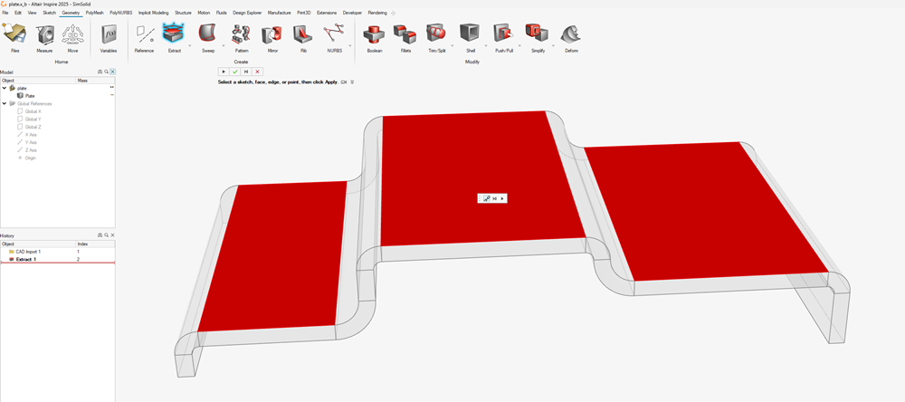
- Select
- Select the surface(s) to extract and click OK in the microdialog.
-
On the Implicit Modeling ribbon, and select the Stochastic
Lattice tool.

- On the Points tab, set the Generation Method to From Part/Mesh.
-
Choose the method to generate points on the selected part.
- Mesh Vertices: extracts the vertices from the visualization mesh of the selected part.
- Sample UV: uniformly samples the surface(s) using
the parametrized spacing as defined in the U Spacing
and V Spacing parameters. Note: UV sampling only generates points when a BRep part or surface is selected.

- On the Edges tab, set the Generation Method to From Part/Mesh.
- Set the Edges mode to Normal at Point to generate edges that project along the surface normal.
-
Use the Start Distance and End
Distance parameters to define how far away from the surface the
edge will start and end. Negative values will project into the surface, and
positive values project away from the surface. These values can be constant,
variable driven, or field driven as shown below.

-
Click OK to accept the point-edge set and begin
thickening the generated edges.
The Stochastic Lattice guide panel is displayed.
-
Define the thickness of the edges using the Strut
Diameter parameter. This can be constant, variable driven, or
field driven.

- To boolean the generated tool bodies with a target body, switch to the Outer Body tab and select the Boolean mode.
-
Use the Target Body collector to pick which body to use
as the target of the boolean operation. There are three boolean options.
- Combine: adds the tool bodies to the selected
body, creating pin-like structures.

- Subtract: removes the tool bodies from the
selected body, perforating the body.

- Intersect: preserves any geometry that is common
to both the tool bodies and selected body.

- Combine: adds the tool bodies to the selected
body, creating pin-like structures.
- Click OK.