
Create an Implicit Warp Map
Map a 2D object to 3D coordinates by specifying the warp via two linked UV grids. One grid defines the UV parametrization of the 2D object, such as an imported image or a slice of a 3D implicit body, and the other grid defines corresponding positions in 3D space.

-
On the Implicit Modeling ribbon, select the
Warp Map tool.

The Warp Map guide panel is displayed.
- From the Target dropdown, select the source of the 2D object that you want to warp, position and drape by positioning the 2D and 3D UV grids.
-
Select the Repetition checkbox to repeat the 2D object,
as when using a linear pattern.
- Enter a value in the U Count box to set the number of times the object repeats in the U direction across the span of the 3D UV grid.
- Enter a value in the V Count box to set the number of times the object repeats in the V direction across the span of the 3D UV grid.
-
Select the Background checkbox to declare a background
value, which is the value adopted by any point that falls outside the span of
the 3D UV grid (which also includes limits in the third parametric direction, W,
if the "Clamp W" option is active - see below).
Enter a value in the Background Value. For example, if the target is an imported grayscale image, pixel values typically fall in the rage [0, 255]. Typically, 0 denotes black and 255 denotes white pixels. You might use these grayscale values to control the amount of local offset on a surface, where black [0] is zero offset, and white [255] is 5 mm offset. By setting the background value to 0, all regions outside of the 3D UV grid will return 0, and therefore not experience any offset.
-
Select the Clamp W checkbox to limit the effect of the
Warp Map in the third parametric dimension, W, which is perpendicular to the 3D
UV grid at every point. Thinking of the 3D UV grid as a surface, "Clamp W" gives
this surface finite thickness to create a volume of influence.
- Enter a value in the Min W box to set the lower limit of volume of influence in the W-direction (negative numbers are behind the 3D UV grid, and positive numbers are ahead of the 3D UV grid. This value should be specified in length units.
- Enter a value in the Max W box to set the upper limit of volume of influence in the W-direction (negative numbers are behind the 3D UV grid, and positive numbers are ahead of the 3D UV grid. This value should be specified in length units.
-
Example workflow for Warp Map-Driven Offsets for Bump Maps.
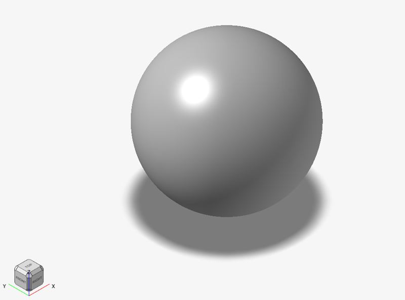
- Start with an implicit body in the scene where you wish to apply a warp
map-driven offset. This might be for adding texture, a logo, or even
text to an existing model.
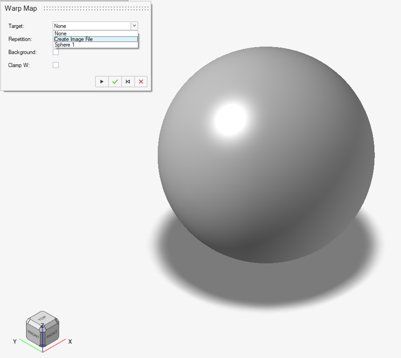
- Select the Warp Map tool and select Create Image
File from the Target
dropdown.
- In the Image context, click the Import icon
 to select a
previously created 2D image that contains the field information for use
in the Warp Map operation. In this example, we are using a wavy pattern
where the grayscale color data will be used to control the amount of
local surface offset on the sphere. Note: The .png file format is required for image imports in the current release.
to select a
previously created 2D image that contains the field information for use
in the Warp Map operation. In this example, we are using a wavy pattern
where the grayscale color data will be used to control the amount of
local surface offset on the sphere. Note: The .png file format is required for image imports in the current release.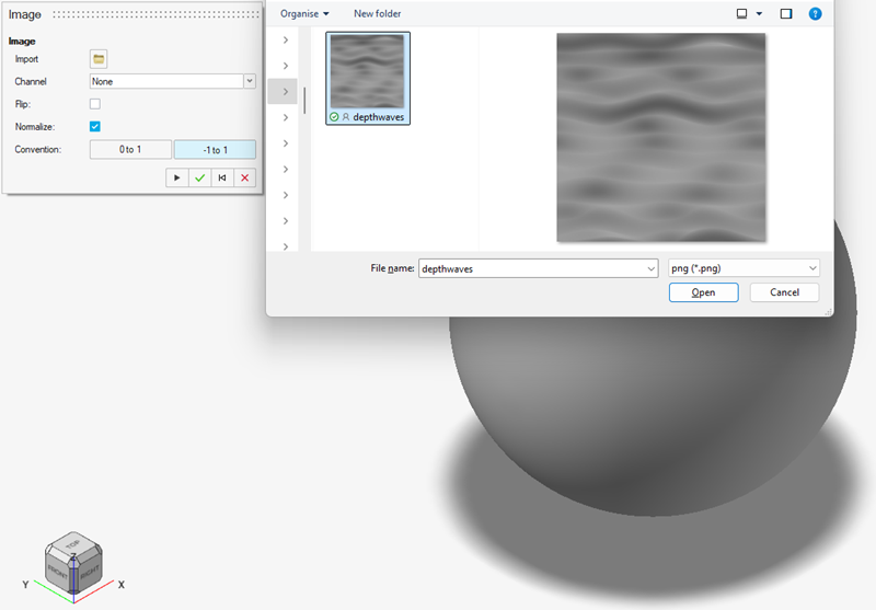
Once you have selected an image, the image will be viewable in the scene in a plane parallel to the global Z plane.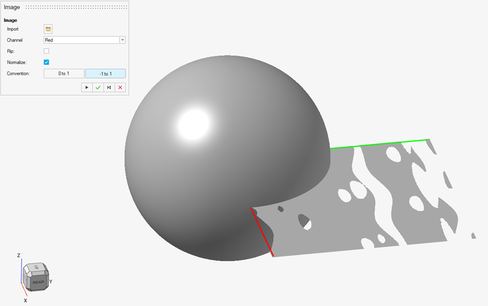 Note: The image may look different to how it looks in reality. This is a because of normalizing and because the image is being viewed as a field rather than an image. This is nothing to be concerned about and you can proceed with the workflow.
 - You can now set the options that determine how data is extracted from
the image. First, select the color Channel from
the image that best describes the information you wish to use:
Red, Green,
Blue, Alpha, and
Grayscale. For the image used in this
tutorial, the grayscale is equally well represented in the red, green,
and blue channels, so we will select the default red channel.
The next option is Flip. This setting enables you to select which pixel intensities will be treated as low numbers and which will be treated as high numbers. Pixel intensity values typically fall in the range [0, 255], where zero represents black and 255 represents white. For this example, we will treat black pixels [0] as denoting zero surface offset and white pixels [255] as denoting a maximum outward offset. This is fine for this workflow, but if we wished to reverse this relationship, the Flip option would recompute the pixel values as 255 minus the pixel values stored in the image, converting black to white and vice versa.
The final option is Normalize, which will rescale the [0, 255] range to a new range. There are two options [0, 1] and [-1, 1]. Implicit modeling tends to treat negative numbers as interior to a solid, and positive numbers as exterior. For this reason, we will use the [1, 1] convention. This is also useful as it will enable us to maintain a view of the image in the scene. If the [0, 1] is used, we will not have any negative numbers, which means there will be no "interior". This will cause the image to disappear as the image view shades the interior (usually in gray) and leaves the exterior empty. The final setup of the Image context should look like this: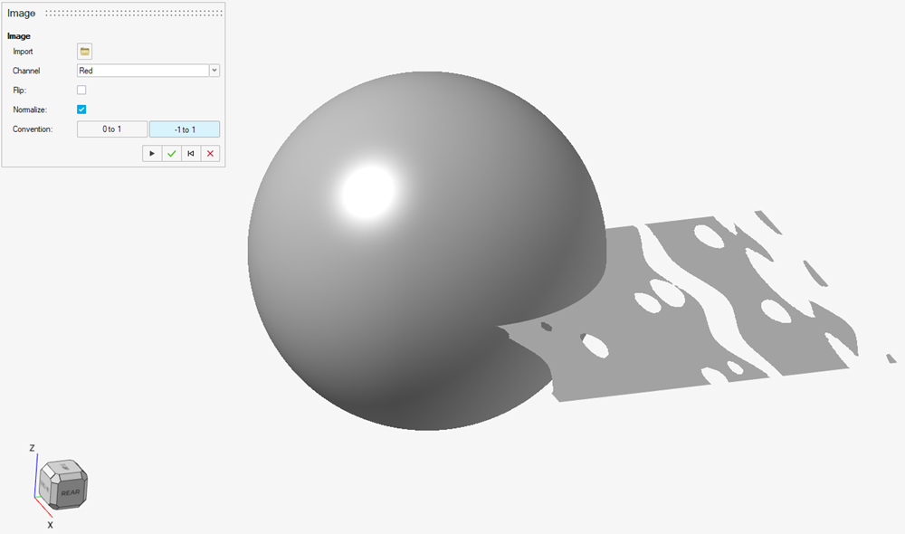
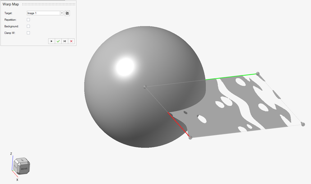
- After clicking OK on the Image context, you will
be returned to the Warp Map context. You will notice a control cage has
been created on the image body, as shown in the following image. You
will also notice the creation coordinate axes on the image where red
represents the parametric coordinate direction U and green represents
the parametric coordinate direction V. The UV coordinates are
intrinsically linked to the control cage which is defined by the small
spherical control points. We will cover more details on editing this
control cage later in the tutorial.
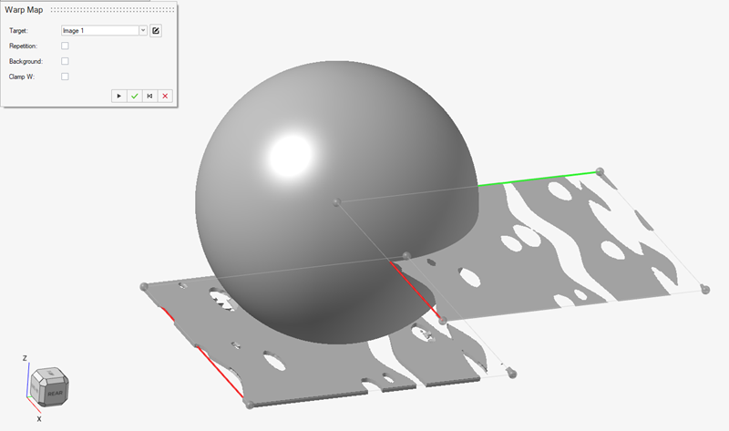
- Now is a good time to select the implicit body that will receive the
Warp Map-driven surface offset. In this example, we will click the
sphere as this is the body we are working with. As soon as you click on
this model, two things will happen. Firstly, a new object appears in the
scene, and this is a deformable Warp Map object that we can drape onto
the sphere. You will notice that this has an equivalent control cage
with its own red (U) and green (V) coordinate axes. There is also a
one-to-one correspondence between the control vertices between this grid
and the grid attached to the image object. At this point, the scene will
look like this, where you can see the new Warp Map body beneath the
sphere and the image object to the right of the sphere:
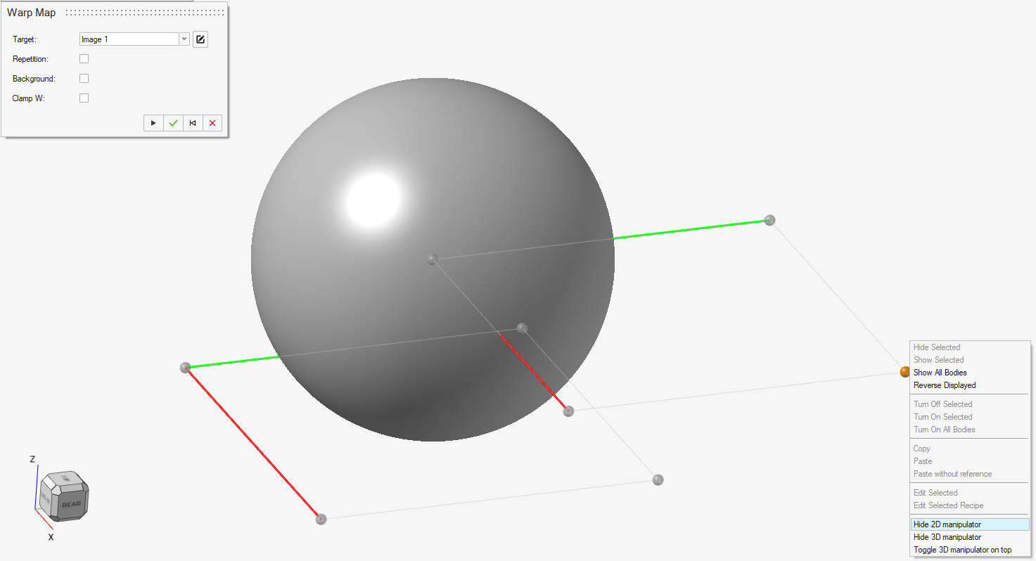
- At this stage, it is best to start draping the Warp Map body onto the
surface of the sphere model. There are many things visible in the scene
at this point, and it can be helpful to hide both the image and the warp
map body for a cleaner view. If you like, you can also hide the control
cage for the 2D image at this point by right-clicking one of the control
cage vertices.
You can now begin positioning the control cage vertices for the 3D grid on the surface of the implicit sphere body. You have complete control over the placement of these vertices. You can select one or multiple vertices and move them by clicking and dragging. If you drag a control vertex over a visible body and release the mouse button, the vertex will snap to the closest visible surface beneath the vertex (looking into the screen). If you do not drag over a visible body and drop the vertex in empty space, it will remain in its plane, which is always parallel to the viewing plane. If you hover over a recognizable feature, such as the end of a curve, it will automatically try to snap to that unless you turn off snapping options. Finally, you can also use the small coordinate system icon in the Positioning pop-up window to precisely place or offset control vertices by entering coordinates.A good starting point is to position the four control cage vertices that represent the corners of the 3D grid, as shown in the following image. Note that you can distort the draped model, which will skew the image when it is draped on the surface of the implicit body. If wish to minimize distortion, try to arrange the corners in a rectangular configuration. The options in the Positioning pop-up window can be very helpful.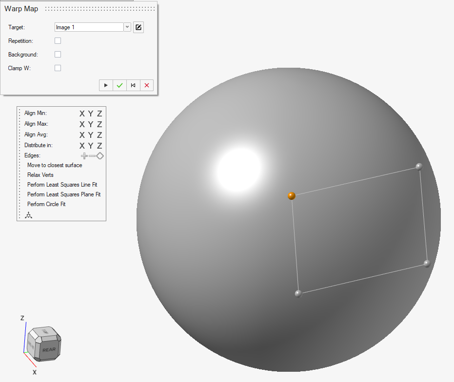
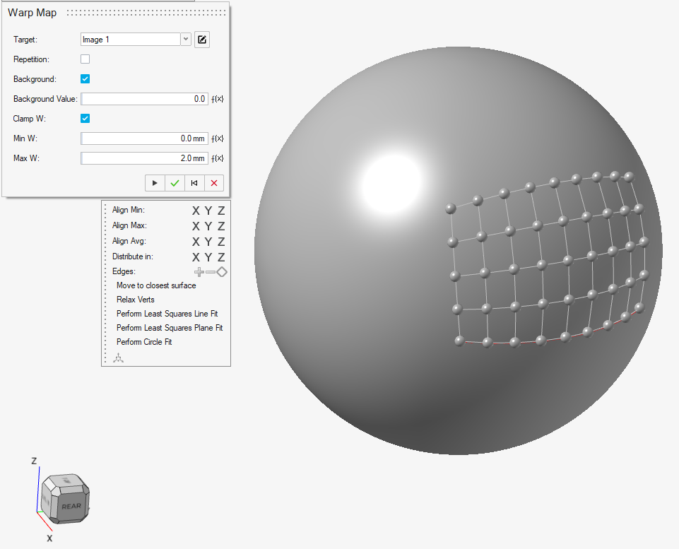
- To get an idea of how well your 3D control cage is draped over the
surface, you can rotate the model and look at the wireframe of the
Control Cage. This should be nicely laid over the surface with enough
cells to capture the local curvature. You can also right-click one of
the control vertices and select Toggle 3D Manipulator on
top to prevent the vertices and edges of the control
cage from showing through the surface of the model (sphere). Within the context of draping onto the sphere, the four corners are not sufficient to capture the surface curvature, and we need to add more vertices to the control cage. You can add these in two ways. First, you can select an edge and then click + in the Positioning pop-up window to split an edge into two edges by adding a new vertex in the middle. Alternatively, hold Shift + left mouse click to split an edge. When a new vertex is added, it is placed at the average position of its two neighbors, and this is not necessarily on the surface of the sphere. To move each vertex onto the surface there are two options. You can either drag each vertex to the desired surface location, or you can select one or several vertices and click the Move to closest surface button in the Positioning pop-up window. This feature will move the point to the closest visible body. It will not move vertices to hidden or suppressed bodies. If you wish to only snap to one body, it may help to have this as the only visible body in the scene. After a small amount of work, we can refine the 3D control cage to look like the following image:
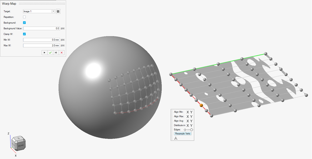
- Now is a good time to unhide the image object and its 2D control cage.
You will see that there is still a one-to-one correspondence between the
vertices of the 2D and 3D control cages. If you are not happy with the
distribution of the vertices on the 2D control cage, you can use the
convenience function Resample Verts that appears
in the Positioning pop-up when you select a vertex on the 2D control
cage.
 Note: If the image overlaps the implicit body receiving the Warp Map (sphere), you can roll back the construction history to just after the image was created and use the implicit modeling Move Bodies tool to relocate it. After doing this, make sure you select Resample Verts so that they also move to the new image location.
 - With the two control cages now set up, this is a good time to create a field that is based on the warp map, and connect this field to an offset operation as this will give you your first accurate view of the warp map effect. You can accept the warp map at this point, safe in the knowledge that you can return to it at any time to tweak various parameters until you are happy with the look.
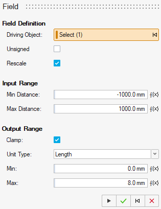
- Click the Field tool in the Implicit Modeling ribbon and clear the
Driving Object input to remove the default
selection. Now select the Warp Map object from the Model Browser. The
Input Range values for the field will be based on the image data. Note: The field does not understand the scale or units of pixel intensities, and will assume that the units are based on length. If you are working in units of meters, you can safely input the range of pixel intensities — in the range [0, 255] — without any modification. If you are using units of millimeters, you will need to multiply these by 1000 i.e. values in the range [0, 255000]. For nonmetric units, you will need to adopt a similar but more complex conversion. If you normalized the pixel intensity values upon creating the image object, the values will either be in the range [0, 1] or [-1, 1]. When working in units of millimeters, the Input Range for the field will therefore either be [0, 1000] or [-1000, 1000].
The values for the Output Range depend on whether you want your surface offset to be inward (engraving) or outward (embossing). The Min sets the deepest offset amount where negative numbers denote an inward movement of the surface, zero is no offset, and positive numbers are outward movement. The Max value should be set to the maximum amount of surface offset you would like and should be larger than the Min value. In this example, we will use a values or 0mm and 8mm for the Min and Max values. This means that black regions of the image will have no offset ,and white regions will have the maximum offset. The final set of inputs looks like this for the example we are working on:
- Click OK
 to confirm these
inputs.
to confirm these
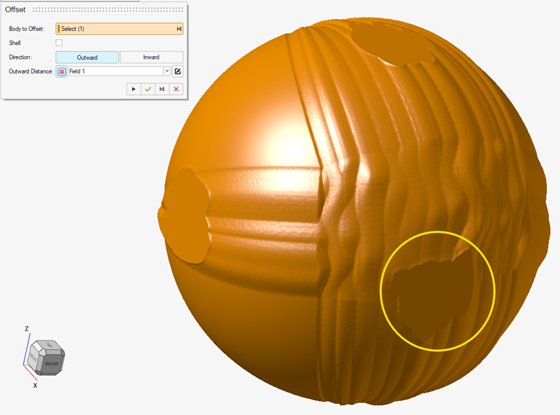
inputs. - Now open the Offset tool
 in the Implicit
Modeling ribbon and select Outward for the offset
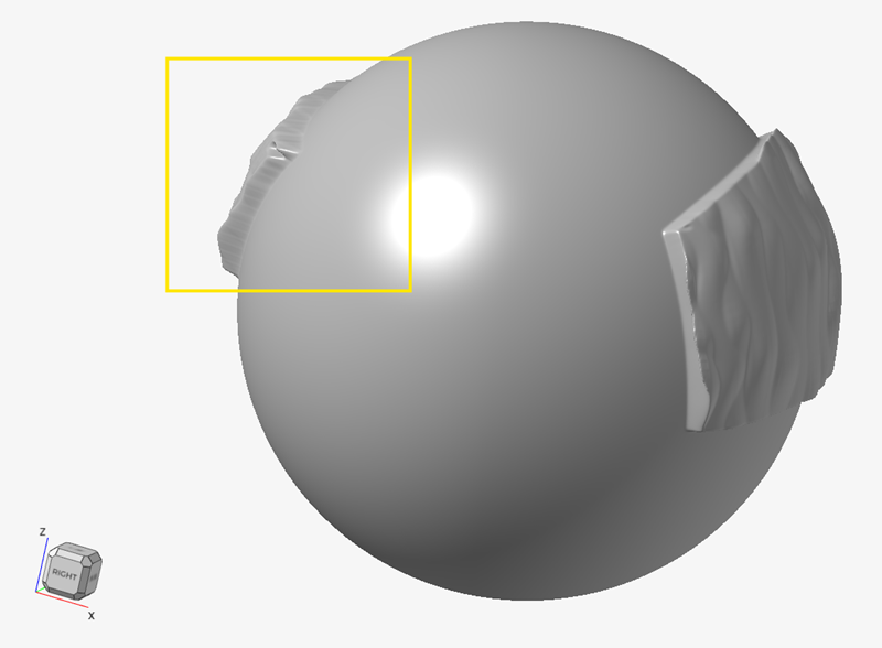
direction. At this point, we advise that you enter the maximum amount
of offset you expect from the Warp Map texture and click
OK
(or press
Enter). This forces the bounding box of the scene to resize to
accommodate the field-driven offset arising from the Warp Map. If you do
not do this, you may experience clipping of the texture, as shown in the
image below. In this example, we will type 8mm
and then click OK
.
in the Implicit
Modeling ribbon and select Outward for the offset
direction. At this point, we advise that you enter the maximum amount
of offset you expect from the Warp Map texture and click
OK
(or press
Enter). This forces the bounding box of the scene to resize to
accommodate the field-driven offset arising from the Warp Map. If you do
not do this, you may experience clipping of the texture, as shown in the
image below. In this example, we will type 8mm
and then click OK
. Now click the Apply
Field button and select the field you have just created.
The texture effect will appear correctly on the model:
Now click the Apply
Field button and select the field you have just created.
The texture effect will appear correctly on the model: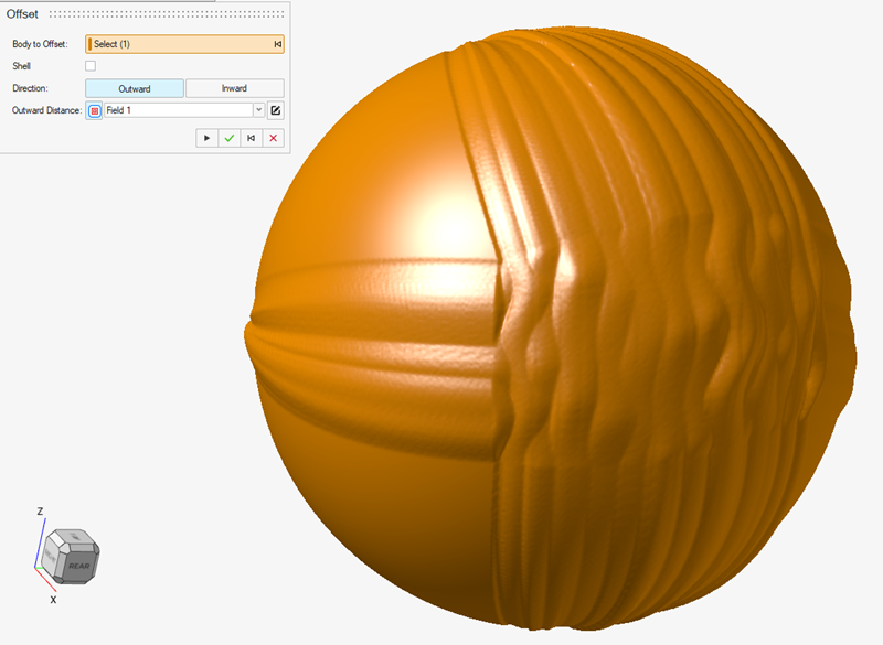
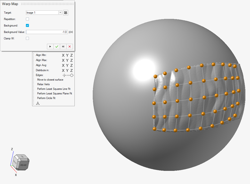
- As shown in the previous step, the texture extends beyond the boundaries of the specified control cage. Given the inputs, so far, this is the correct behavior. To force the texture to stay within the confines of the control cage, you need edit the warp map by right-clicking it in the Implicit Modeling Construction History. You can choose to Edit, which will roll back the history timeline to before the offset operation, or Edit Recipe, which will show the offset texture as you edit the warp map.
- When you edit the warp map, select the Background
checkbox. The Background Value option sets a
pixel value for all points that fall outside of the control cage (and
therefore outside of the selected 2D image region). For this example, we
want no offset, leaving the original surface in the same position
outside of the control cage. Because we normalized the image pixel
values to be in the range [-1, 1], the appropriate background value is
-1, which is the lowest value in this range. This is also the value that
maps to zero offset based on the field created earlier. This change will
confine the texture to the control cage, as shown in the following
images:
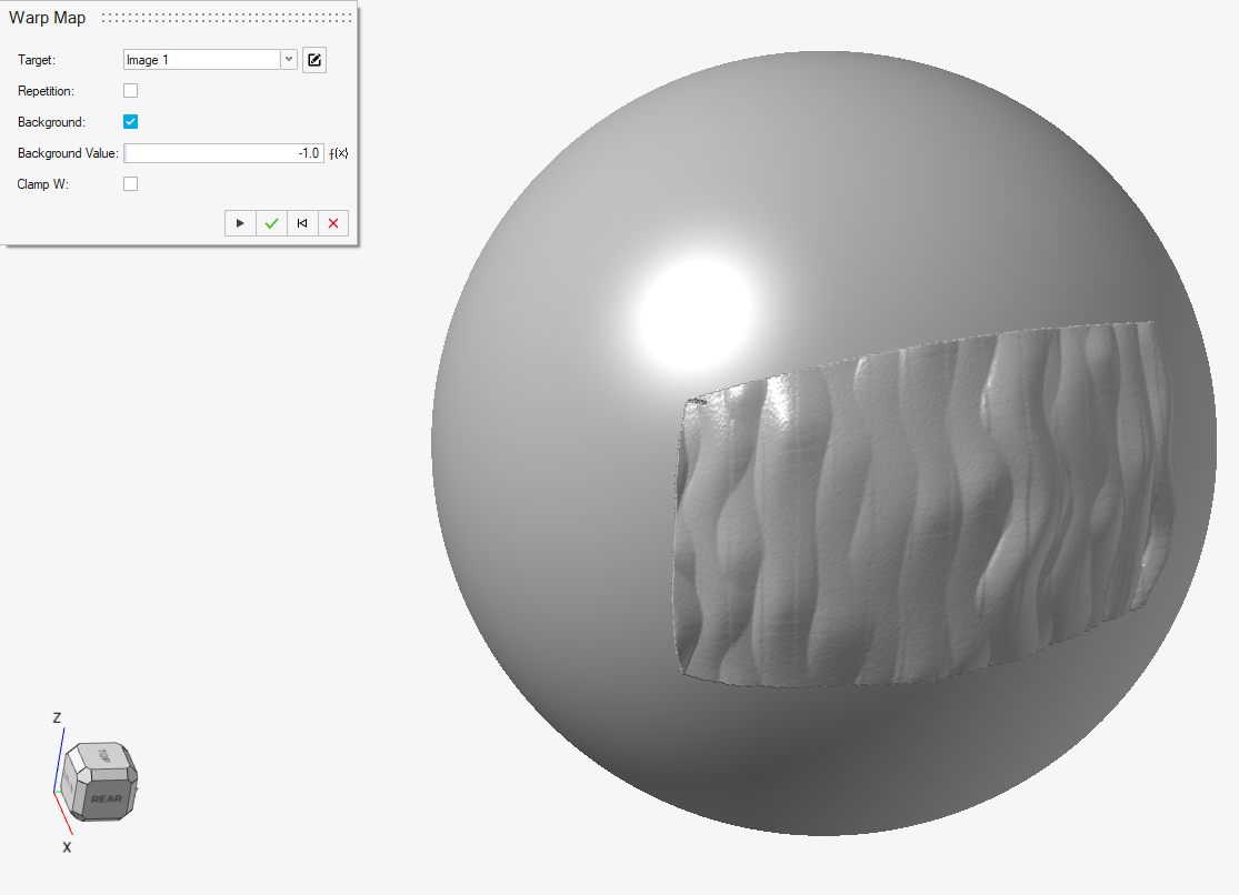
- The texture is now restricted to the extents of the control cage.
However, if you rotate the model, you can see that the texture effect
penetrates through the entire sphere and also appears on the opposite
side.
To prevent this from happening, you need to select the Clamp W checkbox in the Warp Map context. The U and V parametric coordinates move laterally across the control cage, and the W coordinate is always perpendicular to the control cage, much like a surface normal. If Clamp W is selected, any regions of space falling outside of Min W and Max W will be treated as outside of the cage and receive the Background value.In this example, we know that the maximum outward offset is 8mm, and we use this value for Max W. For Min W, a value of zero limits the texture effect to the original surface, where the control cage is located. That is, everywhere on the control cage has a W coordinate of zero. The correct inputs are shown below, and you can see that the texture no longer penetrates through the sphere.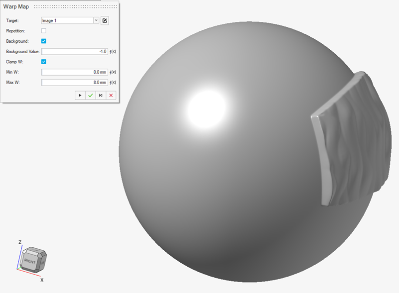
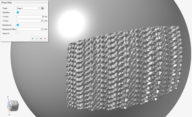
- In many cases, the texture sample image that you use will not be
correctly sized for your model. You can remedy this by using the
Repetition option to tile the texture in the
U and V directions on the control cage. You will need to input the
number of copies of the image you want to see by setting the
U Count and V Count
settings. Repetition works best if the image can be tiled without
visible seams.
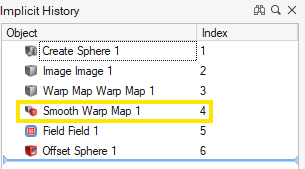
- As a final recommendation, the abrupt nature of adding textures to some
regions and not others can introduce some visual artifacts. Many of
these can be remedied by using the Smooth tools in the Implicit Modeling
ribbon and applying these to the warp map object. The correct place for
this smoothing operation is immediately after the warp map object is
created:
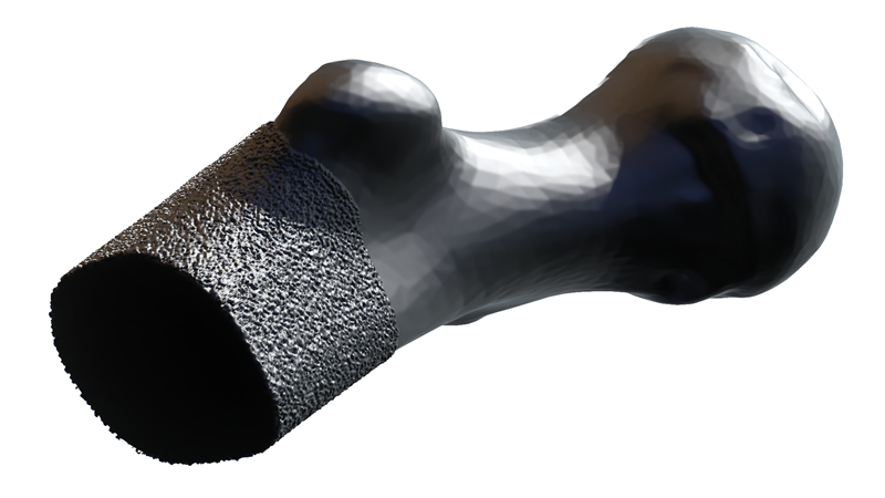
- If you follow the processes outlined in this example, a range of surface
effects can be applied to 3D models using 2D image data as the source.
In the following example, you can see the result of draping an image
containing Simplex Noise onto part of the human anatomy. Textures such
as this can be functional as well as aesthetic. Critically, the design
can be updated/iterated simply by changing the 2D image input. This
opens up new possibilities for computational design using implicit
modeling.
- Start with an implicit body in the scene where you wish to apply a warp
map-driven offset. This might be for adding texture, a logo, or even
text to an existing model.