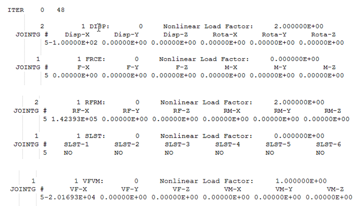
.joint file
The .joint file is an ASCII format results file.
File Creation
This file is created when JOINTD and/or JOINTF I/O Options with OPTI option is specified in an input file which contains JOINTG. Refer to JOINTG Bulk Data Entry.
File Contents
This file contains the Displacements, Forces, and Moments, Reaction Forces, Viscous Damping Forces, and Stop/Lock Status in the joint for the final load increment for each JOINTG ID. Viscous Damping Forces are output only if the PROPERTY field on PJOINTG is set to DAMP. If NLOUT entry is defined, then intermediate load increment results are also printed in the .joint file.
File Format

The .joint file has the following format.
| iter | Iteration | Numlds |
- iter
- Keyword denoting the beginning of a new iteration
- Iteration
- Iteration number
- NumIds
- Number of load increments for which this output is created
| Id | Number_of_els | DISP:Spc_id (or)
FRCE:Spc_id (or) RFRM:Spc_id (or) SLST:Spc_id (or) VFVM:Spc_id |
Nonlinear Load Factor: # |
- Id
- Output identification number for the subcase. This is not the same as the subcase ID used in the input data.
- Number_of_els
- Number of elements for which this output is printed.
- DISP, FRCE, RFRM, SLST, or VFVM
- Keywords indicating that corresponding Displacement or Force results are printed.
- Spc_id
- SID for SPC's referenced by this subcase.
- Nonlinear Load Factor: #
- Load Increment at which the results are output.
| JOINTG # EID | Disp-X | Disp-Y | Disp-Z | Rota-X | Rota-Y | Rota-Z |
- JOINTG # EID
- Element identification number of the JOINTG element EID.
- Disp-X
- Displacement in X-direction for the corresponding JOINTG element EID
- Disp-Y
- Displacement in Y-direction for the corresponding JOINTG element EID
- Disp-Z
- Displacement in Z-direction for the corresponding JOINTG element EID
- Rota-X
- Rotation in X-direction for the corresponding JOINTG element EID
- Rota-Y
- Rotation in Y-direction for the corresponding JOINTG element EID
- Rota-Z
- Rotation in Z-direction for the corresponding JOINTG element EID
| JOINTG # EID | F-X | F-Y | F-Z | M-X | M-Y | M-Z |
- JOINTG # EID
- Element identification number of the JOINTG element EID
- F-X
- Force in X-direction for the corresponding JOINTG element EID
- F-Y
- Force in Y-direction for the corresponding JOINTG element EID
- F-Z
- Force in Z-direction for the corresponding JOINTG element EID
- M-X
- Moment in X-direction for the corresponding JOINTG element EID
- M-Y
- Moment in Y-direction for the corresponding JOINTG element EID
- M-Z
- Moment in Z-direction for the corresponding JOINTG element EID
| JOINTG # EID | RF-X | RF-Y | RF-Z | RM-X | RM-Y | RM-Z |
- JOINTG # EID
- Element identification number of the JOINTG element EID
- RF-X
- Reaction Force in X-direction for the corresponding JOINTG element EID
- RF-Y
- Reaction Force in Y-direction for the corresponding JOINTG element EID
- RF-Z
- Reaction Force in Z-direction for the corresponding JOINTG element EID
- RM-X
- Reaction Moment in X-direction for the corresponding JOINTG element EID
- RM-Y
- Reaction Moment in Y-direction for the corresponding JOINTG element EID
- RM-Z
- Reaction Moment in Z-direction for the corresponding JOINTG element EID
| JOINTG # EID | SLST-1 | SLST-2 | SLST-3 | SLST-4 | SLST-5 | SLST-6 |
- JOINTG # EID
- Element identification number of the JOINTG element EID
- SLST-1
- Stop/Lock Status in direction 1 for the corresponding JOINTG element EID
- SLST-2
- Stop/Lock Status in direction 2 for the corresponding JOINTG element EID
- SLST-3
- Stop/Lock Status in direction 3 for the corresponding JOINTG element EID
- SLST-4
- Stop/Lock Status in direction 4 for the corresponding JOINTG element EID
- SLST-5
- Stop/Lock Status in direction 5 for the corresponding JOINTG element EID
- SLST-6
- Stop/Lock Status in direction 6 for the corresponding JOINTG element EID
| JOINTG # EID | VF-X | VF-Y | VF-Z | VM-X | VM-Y | VM-Z |
- JOINTG # EID
- Element identification number of the JOINTG element EID
- VF-X
- Viscous Damping Force in X-direction for the corresponding JOINTG element EID
- VF-Y
- Viscous Damping Force in Y-direction for the corresponding JOINTG element EID
- VF-Z
- Viscous Damping Force in Z-direction for the corresponding JOINTG element EID
- VM-X
- Viscous Damping Moment in X-direction for the corresponding JOINTG element EID
- VM-Y
- Viscous Damping Moment in Y-direction for the corresponding JOINTG element EID
- VM-Z
- Viscous Damping Moment in Z-direction for the corresponding JOINTG element EID