Lattice Design: Implicit Modeling vs. Traditional CAD
A comparison of designing lattices with implicit modeling versus traditional CAD.
Lattice Design with Traditional CAD
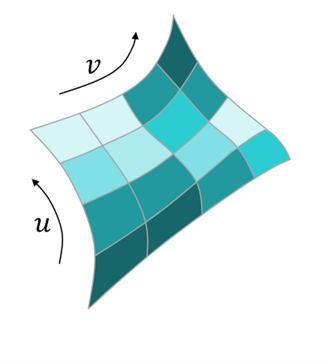
- Construct a series of NURBS surface patches.
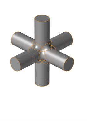
- Assemble these into a lattice unit cell.
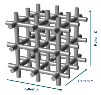
- Then pattern that unit cell in 1-, 2-, or 3-dimensions to form a lattice.
 |
 |
 |
Lattice Design with Implicit Modeling
Inspire’s implicit modeling approach uses a fundamentally different means of describing geometry to offer a suite of tools that enable you to create vastly more complex lattice structures or other high surface-area-to-volume ratio shapes.
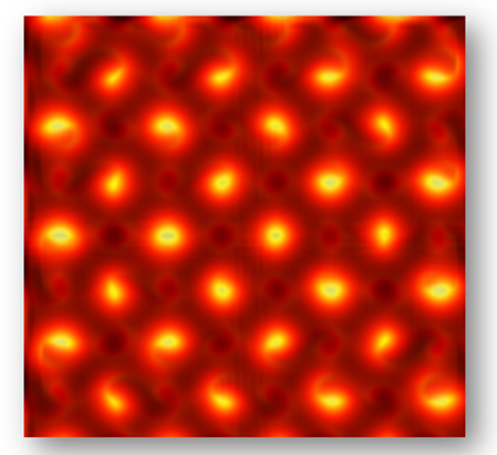
Implicit modeling makes use of implicit surfaces. Implicit surfaces are perhaps best thought of as a field rather than a surface—at every point in space the field defines a scalar value, often some notional or actual distance to the nearest point on the surface. So, if we define the implicit surface as passing through all points in the field where the scalar values equal, say, zero, we call this surface the zero level-set of the field. The zero level-set can be computed and rendered as a single isosurface, which completely removes the need to compute and manage all of the watertight intersections that were present when stitching NURBS patches together. Another key point is that points on one side of the isosurface will have a positive scalar value, and points on the other will have negative scalar values. As such, we can run instant inside-outside checks for points in space, and we know how far away the surface is. This makes implicit modeling ideal for hardware acceleration on the GPU for both computation and rendering purposes.
 |
 |
In addition to significantly faster compute times, creating lattices using implicit modeling comes with some other very important benefits.
- In addition to strut lattices, which comprise nodes and struts between them, implicit modeling can also produce Surface Lattices, which are typically Triply Periodic Minimal Surfaces (TPMS), like a Gyroid. It is very difficult to accurately reproduce these using parametric surfaces, like NURBS.
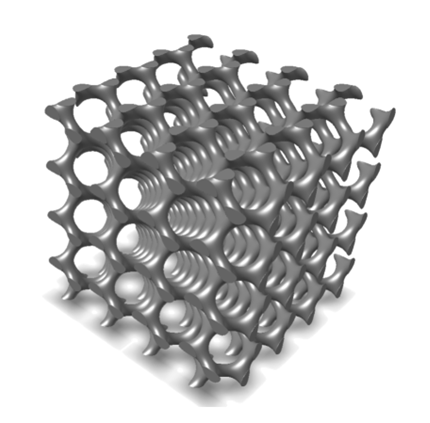
- Previously, regular lattices were created by copying and translating a unit
cell of geometry in, say, the x-, y-, and z-directions (see image above).
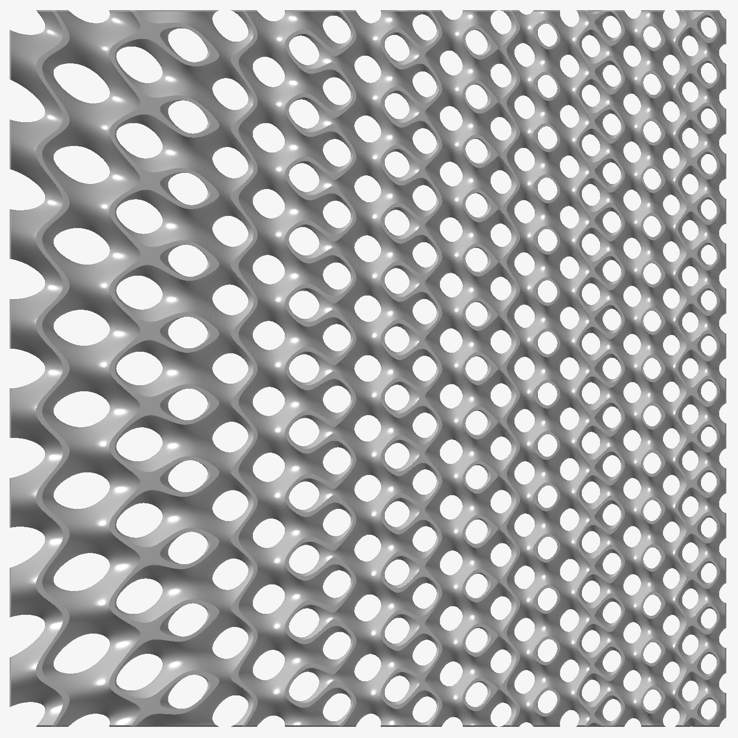
This means that there is no facility to smoothly increase the number of unit
cells across the lattice. No such restriction applies in implicit modeling,
where the number of unit cells can vary smoothly across the lattice
structure, as below.
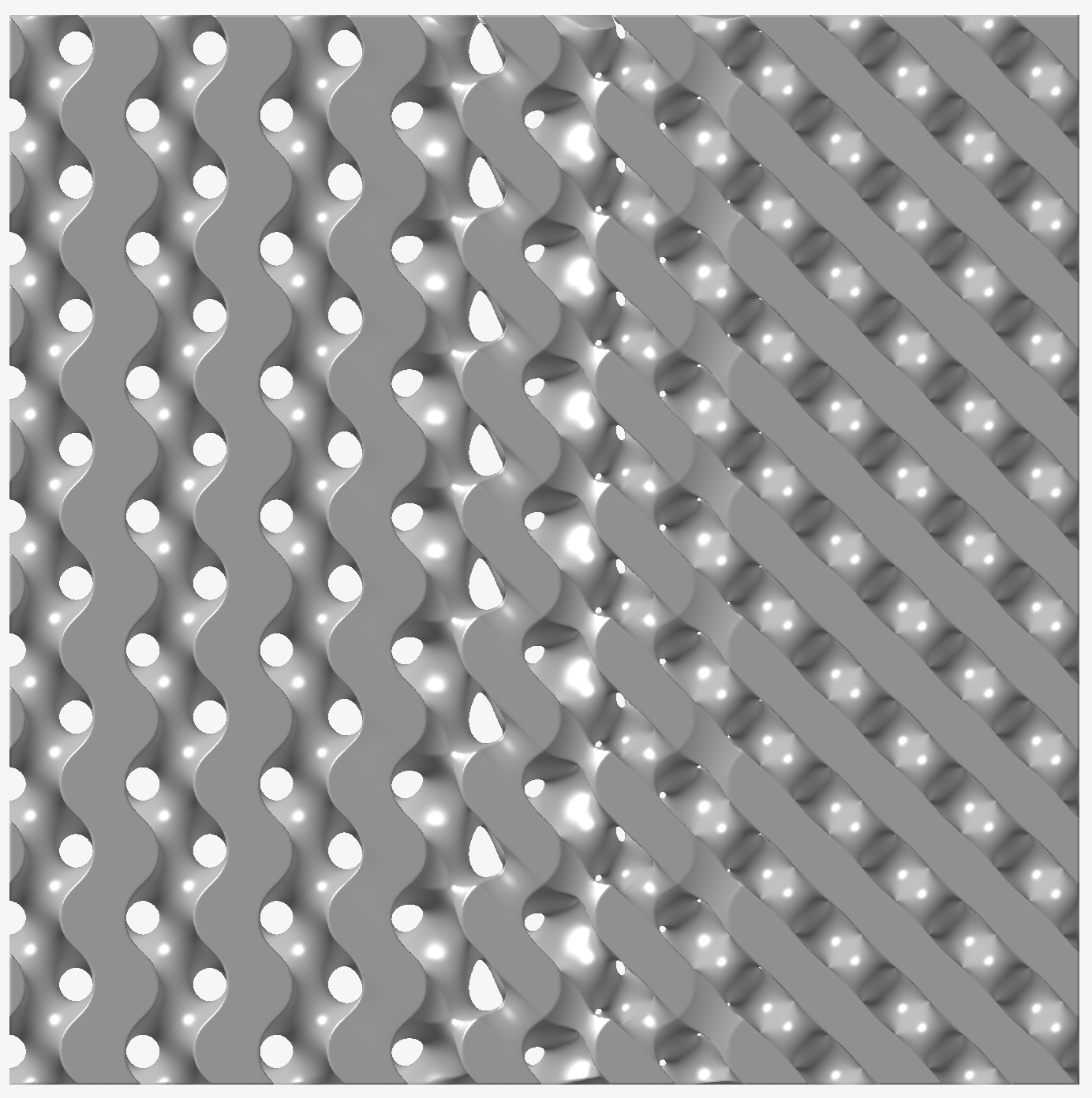
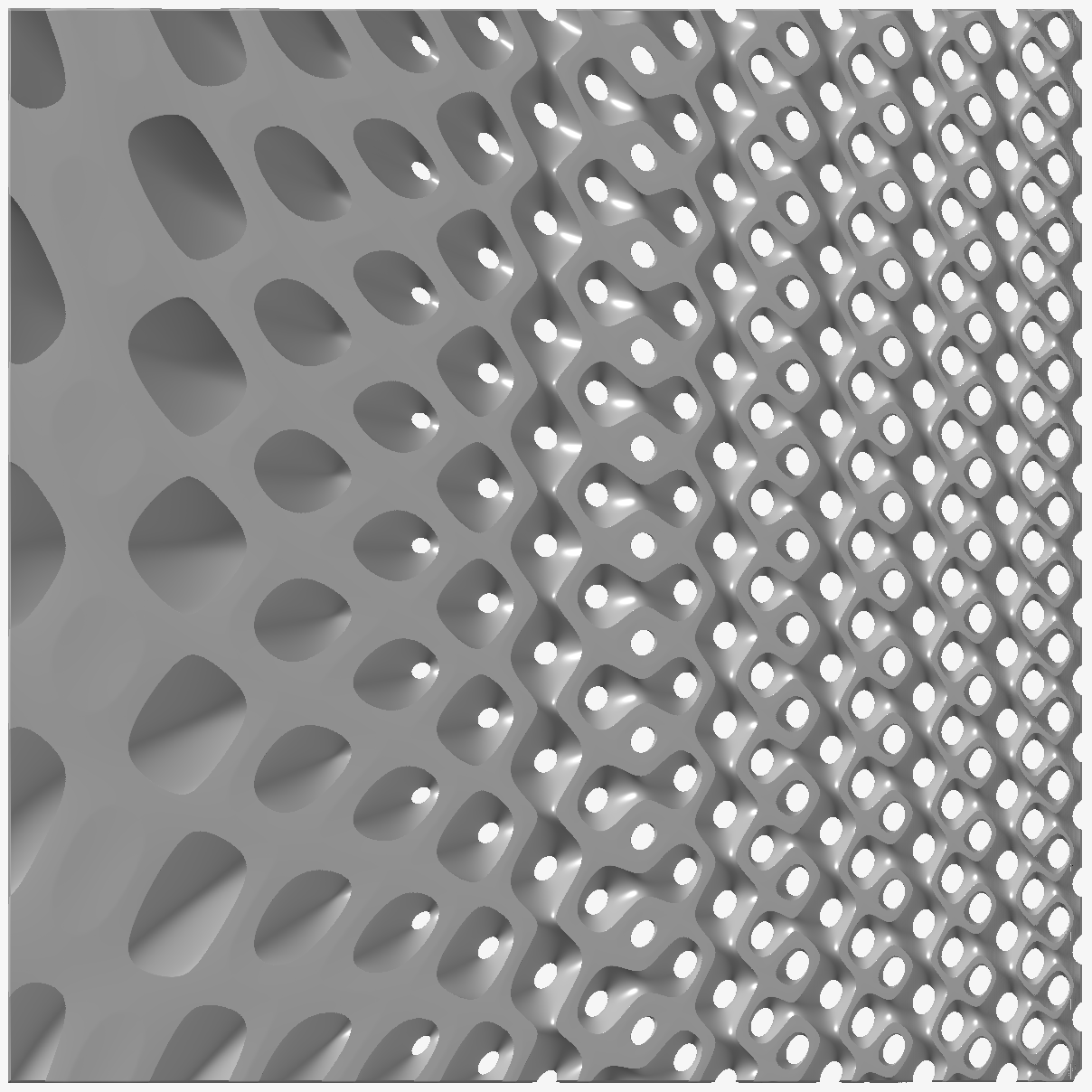
- It is possible to layer gradient effects using field-driven design. In the
image below, the lattice experiences an decrease in relative density and
unit cell size from left to right.
- It is even possible to combine lattice design with morph operations to
smoothly transition from one lattice unit cell into another. The image below
shows a Gyroid morphing into a Schwarz D lattice, moving from left to
right.