LC Card
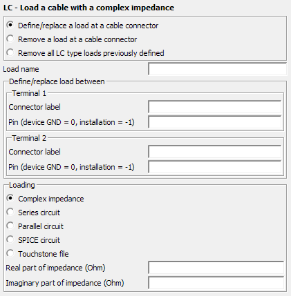
The LC card specifies complex, series and parallel circuits applied between connector pins and also between a connector pin and ground.
On the Source/Load tab, in the Loads /
networks group, click the ![]() Load icon. From the drop-down list, click the
Load icon. From the drop-down list, click the ![]() Load cable (LC) icon.
Load cable (LC) icon.

Parameters:
- Define/replace a load at a cable connector
- Define/replace a load at a cable connector with the following parameters.
- Remove a load at a cable connector
- A load can be removed between two connector pins by defining the Connector label and Pin.
- Remove all cable loads previously defined
- All previously defined LC type loads are removed.
- Load name
- The name of the load.
- Define/replace load between
- A load can be placed between two connector pins by specifying the Connector label and pin number for both connectors. If the pin is set to 0, the connector pin is connected to the local circuit device ground. If the pin is set to -1, the connector pin is connected to the global installation.
- Complex impedance
- Define the real and imaginary parts of the complex impedance in Ohm using Real part of impedance (Ohm) and Imaginary part of impedance (Ohm) respectively.
- Series circuit
- The resistor value in Ohm, inductor value in Henry and the capacitor value in Farad to be added as a series circuit.
- Parallel circuit
- The resistor value in Ohm, inductor value in Henry and the capacitor value in Farad to be added as a parallel circuit.
- SPICE circuit
- Specify the name of a one-port SPICE circuit to define a load between two pins. Define the SPICE circuit using the SC card.
- Touchstone file
- Specify a one-port Touchstone file (.s1p,
.z1p, .y1p) to define a load.Note: If the load is added to a port that has a voltage source, the load is placed in series with the voltage source.
For detailed conductor to cable connector pin relation, see the AK card.