AC Card
This card inputs data from a .rsd file containing the geometry of a transmission line or PCB structure and the current distribution along this line or on the PCB for one or more frequencies.
On the Source/Load tab, in the Ideal sources
group, click the ![]() Impressed current
icon. From the drop-down list, click the
Impressed current
icon. From the drop-down list, click the ![]() Cable source (AC) icon.
Cable source (AC) icon.
Parameters:
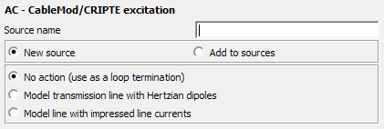
- New source
-
This card inputs data from a .rsd file containing the geometry of a transmission line or PCB structure and the current distribution along this line or on the PCB for one or more frequencies. A new excitation is defined which replaces all previously defined excitations.
- Add to sources
- A new excitation is defined which is added to the previously defined excitations.
- No action
- No execution, do not read the .rsd file. This option is used to specify the end of the frequency loop, see comments below.
- Model transmission line with Hertzian dipoles
- The line geometry, frequency and currents are read from the .rsd file, and the line is modelled with an array of Hertzian dipoles (see the A5 card). The number of dipoles per line segment is specified with the parameter Number of dipoles per transmission line. Note that this model is only valid if the line segments do not make electrical contact with any conducting surfaces. (All the segments in the .rsd file must be of the type intern and not loaded.)
- Model line with impressed line currents
- The line geometry, frequency and currents are read from the .rsd file, and the line is modelled with a continuous current distribution using one AI card per line segment. (The AI cards are created automatically by PREFEKO when importing the .rsd file.) If a line segment has a loaded endpoint it is automatically modelled by an AV card to allow the electrical contact. The radius of the impressed current element can be set in the parameter Radius of impressed current. This parameter is optional and is passed on to the AI and AV cards. If the parameter is zero or empty a current filament approximation is used.
- Source translation (directions)
- When importing transmission line currents from CableMod or CRIPTE or PCB currents from PCBMod, then the coordinate system of these programmes as represented in the .rsd file is used and the source is imported at this position in Feko. Here an offset can be specified which translates the source in the X direction, Y axis and Z axis. Standard Feko units are used for these offsets (that is metres, but scaled accordingly if a factor is set at the SF card). Note that the units as specified in the .rsd file are not applicable here for the translation parameters (only to the import of the data).
- Rotation about axes
- Like the translation described above, an imported source can here be rotated and thus positioned arbitrarily. The rotation angles are in degrees, and uses the same definition as the AR and CG cards.
- File name
- The name of the .rsd file.
- Use adaptive frequency sampling
- Only read the minimum and maximum frequency from the .rsd file and obtain a continuous solution in this frequency band using adaptive frequency sampling. If this option is used only one AC card is permitted in the .pre file and no FR cards.
- Maximum number of discrete frequency points
- When using adaptive frequency sampling, the maximum number of sample points can be specified here. See also the discussion on adaptive frequency sampling for the FR card.
- Minimum frequency stepping
- When using adaptive frequency sampling it could be necessary to specify the minimum allowable frequency between samples. See also the discussion on adaptive frequency sampling for the FR card.
If the imported .rsd file contains currents for several frequencies, the option New source must be chosen as the AC card then results in a frequency loop and currents with different frequencies cannot be superimposed. (If it is not chosen, PREFEKO will give an error). The frequency is defined in the .rsd file, thus the preceding FR cards are ignored when processing an AC card.
- AC: importing a new .rsd file, or using the No action (use as a loop termination) option
- FR: manually setting a new frequency
- EN: end of the Feko input file
AC ... ** Read the *.rsd file
FE ... ** Calculate the near field
EN ** End** Excitation by a line current
AC ... ** Read the *.rsd file
FE ... ** Calculate the near field
OS ... ** Output the currents
** Excitation by a plane wave
FR ... ** Set the frequency and terminate
AC loop
A0 ... ** Specify plane wave excitation
FE ... ** Calculate the near field
OS ... ** Output the currents
** End
EN