LS Card
This card assigns a series circuit of discrete elements in series to a segment.
On the Source/Load tab, in the Loads /
networks group, click the ![]() Load icon. From the drop-down list, click the
Load icon. From the drop-down list, click the ![]() Series load (LS) icon.
Series load (LS) icon.

Parameters:
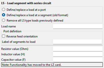
- Define/replace a load at a port
- Define/replace a series circuit at the port with name Port defined using a PT card.
- Define/replace a load at a segment (old format)
- Define a load with the following parameters.
- Remove all LP type loads previously defined
- This LS card does not define a load, but rather all previously defined LS loads are deleted. All the other input parameters of this card are ignored.
- Load name
- The name of the load.
- Reverse feed orientation
- By default, the vector of the voltage is orientated in the direction from the start of the segment to its end (the direction in which it was created). When this option is checked, the vector of the voltage is orientated in the opposite direction. (This is the direction of the current flow through the segment. The internal EMF (electromagnetic force) of the impressed voltage source is in the opposite direction.
- Label of segments to load
- All segments with this label are assigned the series circuit values specified below.
- Resistor value
- Value of the resistor in .
- Inductor value
- Value of the inductor in H.
- Capacitor value
- Value of the capacitor in F.
The impedance is given by
If a capacitance of zero is selected, it is interpreted as infinite capacitance, therefore in the case of the series circuit it is zero.
The LS card may be combined with the LD, LP, LZ and the SK cards, but only one LS card may be used per label. If a second LS card is used, it replaces the values entered by the first one. This card has no significance for surface elements, even when these are assigned the same label.