Meshing the Geometry
Mesh the geometry to create a first discretised representation of the model.
-
On the Mesh tab, in the 2D Mesh
group, click the
 Surface Mesh icon.
-
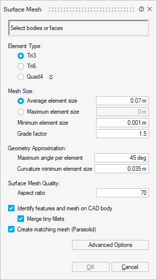
On the Surface Mesh dialog, specify the following:
- Element type: Tri3
- Average element size: 0.07 m.
- Minimum element size: 0.001 m
- Grade factor: 1.5
- Maximum angle per element: 45 deg
- Curvature minimum element size: 0.035 m
- Aspect ratio: 70
- Select the Create matching mesh (Parasolid) check box.
-
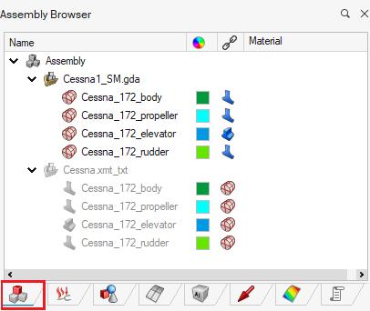
Select the model using one of the following workflows:
- In the graphics window, left-click and drag to select the whole model.
- In the Assembly Browser, select Cessna.xmt_txt.
-
Click OK to close the Surface Mesh
dialog.
Note: If the OK button is disabled, select the model.
-
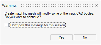
A Waning dialog is displayed; click Yes to
continue.
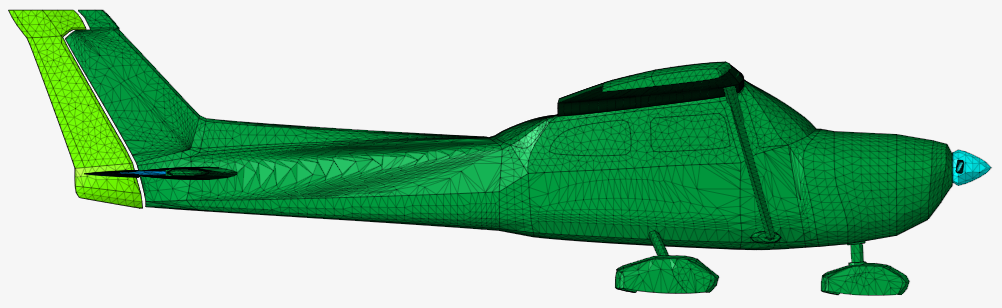
The meshed Cessna model is displayed in the graphics window.