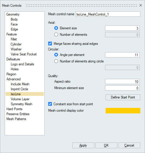
Iso-Line Mesh Control
Introduction
Iso-Line Mesh Control is for placing mapped mesh (90 degree triangulation) on cylindrical \ conical faces that are trimmed (with cutouts and non-circular boundary edges) / non trimmed (with four sided faces and circular edges defining the boundary). The mapped mesh is created for a given size/seed in axial and circular directions.
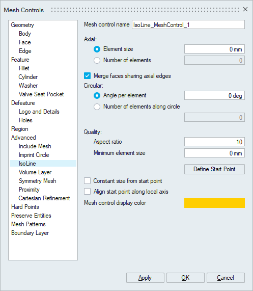
- Axial
Axial mesh size or mesh seeds is used to control the element size along the length of the trimmed/non trimmed cylindrical Faces.
- Merge Faces Sharing Axial Edges
Selected faces will be merged to a single face when Merge faces sharing axial edges option is enabled.
- Circular
Number of nodes along the circular direction can be controlled by using mesh angle or mesh seeds. The mesh angle refers to the angle subtended by a circular spanning element edge from the axis of cylindrical face.
- Quality
- Aspect Ratio: Aspect ratio determines the quality of mesh. Aspect Ratio value varies from 1(equilateral element) to infinity(flat element). The default aspect ratio value is 10.
- Min Element Size (Minimum Element Size): The mesh will have no elements with an edge length smaller than the Minimum Element Size. The default value is 0.
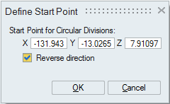
- Define Start Point: User can define the start point of the IsoLine mesh pattern. When start point is defined, the node placement in axial and circular direction start from this specified point. The circular node placement direction can be reversed using the option Reverse Direction.
- Constant Size from Start Point
If the Constant Size from Start Point option is enabled, the element lengths in the circular and axial directions will maintain input sizes constantly along the spawn of each direction.
Suppose if the length of the cylinder is 10units and the mesh size in axial direction is given as 3units. If Constant Size from Start Point option is enabled, then it will create 4 elements on the axial direction. Here the first 3 elements will be of uniform length (3 units) and 4th element will be of length 1unit.
If Constant Size from Start Point is disabled, then it will create 3 elements in axial direction with uniform length of 3.33units.
If the input is in terms of the seeds in axial / circular direction, then the elements will be created with uniform distance.
The basic behavior of all parameters are shown following example on a simple cylindrical surface.
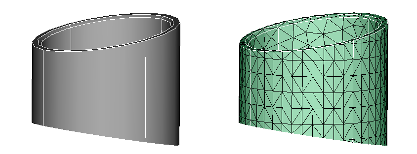
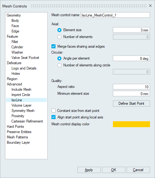
Example 1
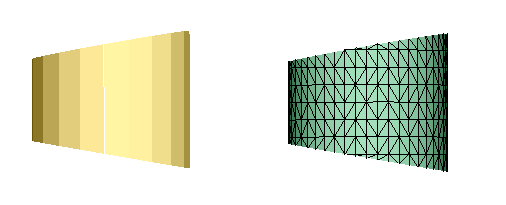
IsoLine Control on trimmed cylindrical face with axial mesh size 3mm and angle 8 degrees.

Example 2
Below Example with Constant Size from Start Point toggle ON:
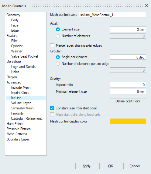
In the output we can observe the non uniformity of size near the edge at highlighted area. This is because the face has a circular span that is not a multiple of 8 degrees. So the last segment is less than 8 degrees and so appears non-uniform. Note that the cylinder is made of 4 separate surfaces.
Example 3
Constant size from start point toggle ON with Merge faces sharing axial edges toggle ON:
To avoid the creation of the thin layer of elements, as shown above, the faces can be merged (note 360 is a multiple of 8) at the time of meshing by turning on the Merge faces sharing axial edges flag.

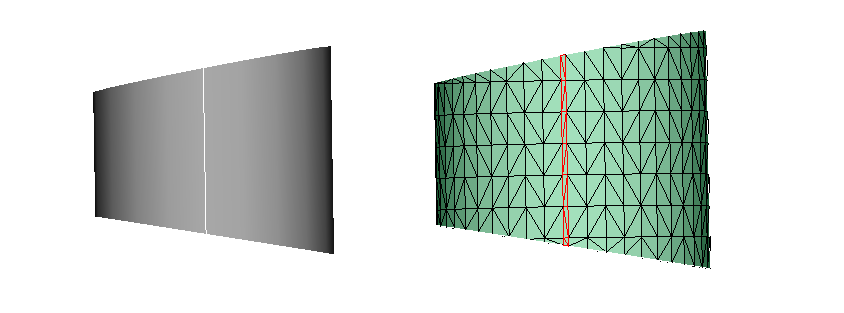
Example 4
Constant size from start point option With Merge faces sharing axial edges and Start Point:
Enabling the Constant size from start point option will allow user to pick a start Point. Once a start point is selected, an arrow displays the direction of the mesh flow in the circular direction. The mesh with nodes aligned in axial direction along the start point can be observed in following example.
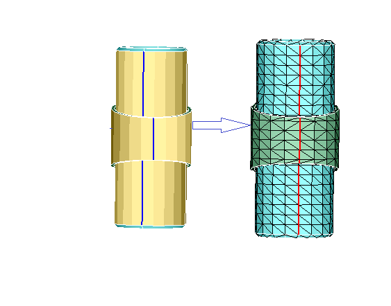
In following picture first mesh with overlap on cad geometry shows the non alignment of
mesh (in red line) with that of geometrical edge (in blue line), where we can get the
alignment on to geometrical edge by selecting the Start Point on the geometrical edge as
show in the second mesh in the below example. 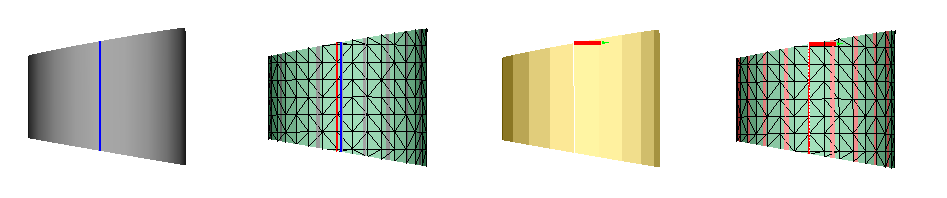
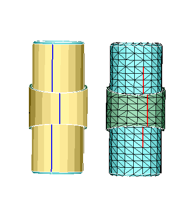
Example 5
IsoLine control with "Align start point along local axis":
Enabling this option will result in same mesh seeding in circular direction, even if the scribe lines are different. The following example shows the same mesh seeding obtained even when the scribe lines are different. Refer the Start Point Documentation for logic used in finding the start point for Isoline mesh control with "Align isoLine start point along local axis".
In following Example, control is applied on two component faces, where the topological edges are not aligned.
In the above output mesh, we can observe the seam lines are following existing topological edges having on aligned pattern.
With "Align start point along local axis" option is enabled, we can see the aligned pattern in radial direction in the below mesh output.
- This option will work along with “Merge faces sharing axial elements” option.
- Align start point will work only for fully closed cylinders.
- If a start point is defined using the “Define start point” option, it will be used and the “Align start point along local axis” will be ignored.
By summarizing all the above examples, it is observed that, in the default behaviour of IsoLine option, we get the uniformly placed iso-mesh flow pattern based on input parameters. Whereas with Constant size from start point enabled, the non-uniform size in last layer of mesh can be induced due to exact placing of mesh in axial and circular direction. Also, the starting point and direction of flow can be controlled using reference point option and pattern alignment using Align start pint along local axis option.