Include Mesh
Introduction
When a solid is meshed, the density of the mesh can be controlled by options available under Mesh Control. A new Mesh Control is added which will allow an existing mesh to be used over a portion of the solid being meshed. A typical use case will be an assembly of parts being meshed and a matching mesh is desired where the parts overlap. This will work if when a part is meshed, it can pick up an existing mesh from the adjacent part that has overlapping geometry. Another use case is when remeshing a solid that has been modified locally. Here the mesh where the geometry has not been modified can be reused. Few examples, down below, will show the power and limitations of this option.
Since this is new technology that is being developed, one has to understand its limitations and be careful in using it in the context this is being recommended. The proper use of this option will require:
- The mesh to be included and the mesh size on the solid where the included mesh will replace should have a mesh size that is similar.
- The boundaries of the included mesh need not match the boundaries of surfaces in the solid. It can overlap part of a surface on the solid.
- The elements on the included mesh should overlap the geometry, completely. They cannot partially overlap the geometry, in other words, partially overlap and the remaining portion protrude outside the geometry.
- The included mesh should be a separate body.
- All node and element ids in the included mesh will be preserved.
Limitations
The limitations of this approach include:
- Works only when meshing CAD models (Parasolid/ProE/Catia/STEP) and not when remeshing a mesh body.
- Does not support Tri6 mesh.
- Topological edges in the included mesh should have more than one node, i.e., a closed edge with a single vertex is not supported. This can be easily fixed by adding a vertex to an edge in the include mesh body.
Examples
Examples are provided to show how to use this option and the limitations.
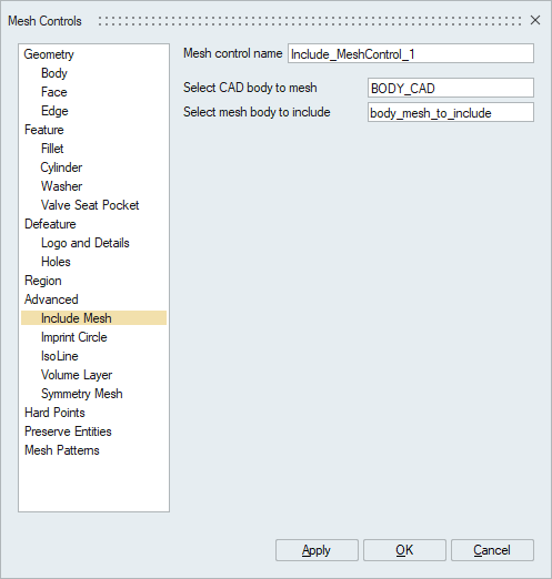
- Implementation UI
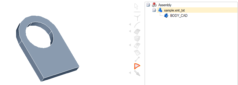
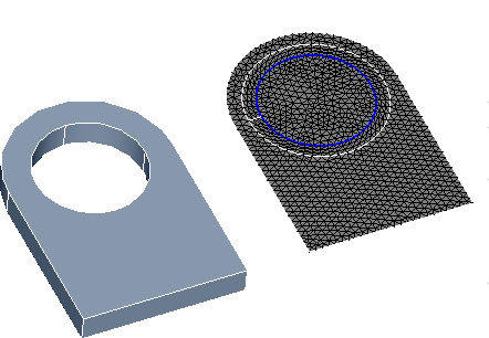
- Geometry Import (solid Body)
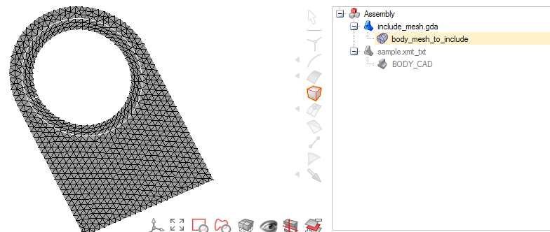
- Include Mesh Import
- Application of Mesh Control by selecting the CAD body and body Mesh to include
under Include Mesh Option.
-
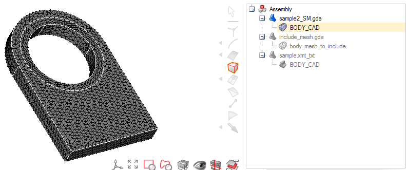
On Meshing the mesh is included in the output mesh
- Geometry Import (solid Body)
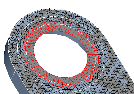
- Invalid Case 1
Invalid case, where the high lightened region in above figure doesn't have underlying geometry in the applied body.
-
Invalid Case 2
Invalid case, where the tri-elements in the include mesh protrudes outside the geometry of the CAD body.