Fillet Mesh Control
Introduction
Fillet Mesh Control is used to control the mesh over fillets along the length and the curve direction. The fillet faces in a body can be identified by selecting the body on display window and Right Click | Select Features .
The user can apply the fillet mesh control either to the selected faces or bodies. In order to apply fillet mesh controls to bodies, the "Radius Range" option should be turned on.
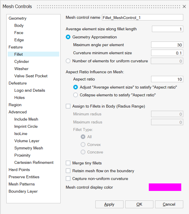
Average element size along fillet length
This is used to define the element length along the length of the fillet.
Geometry Approximation
- Maximum angle per element: The approximation of a geometry is related
to the angle made by an element edge on a perfect circle. Suppose the angle
is 45 deg, then this will approximate a circle by 8 elements. If the angle
is 30 deg, then this will approximate a circle by 12 elements. This same
measure is extended to an arbitrary curved surface.
Based on the angle specified, the number of rows of elements through the curvature of the fillet will be determined. If the fillet varies in curvature, then the number of rows will change accordingly.
-
Curvature minimum element size: The mesh approximates the geometry by varying the mesh size as a function of the curvature. Such geometry approximation cannot result in a mesh size smaller than Curvature Minimum Element Size.
Number of elements for uniform curvature
Number Of Elements can be specified instead of the angle to create a specified number of rows of elements through the fillet curvature. Note that the number of rows will remain same even if the fillet varies in curvature.
Aspect Ratio Influence on Mesh
- Aspect ratio: Aspect ratio determines the quality of mesh. Aspect Ratio value varies from 1(equilateral element) to infinity (flat element).
- Adjust "Average element size" to satisfy "Aspect ratio": This option would adjust the length along fillet to make sure the aspect ratio is satisfied.
- Collapse elements to satisfy "Aspect ratio": This option would collapse the elements which are failing for aspect ratio.
Assign to Fillets in Body (Radius Range)
This toggle is used to apply fillet mesh control to a body. The user has to specify the fillet radius range. The mesher will extract the fillets within this range at the time of meshing and create the mesh.
Fillet type:
This option gives flexibility to apply the fillet mesh control to concave or convex fillets on the selected body.
Using Right Click | Select features, the list of faces for which the fillet mesh control will be applied can be cross-checkedExample 1
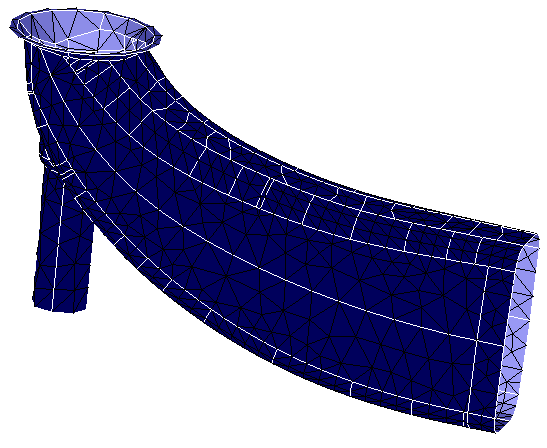
Fillet faces (0 to 20 radius) are identified using Select features option and fillet mesh control is applied.
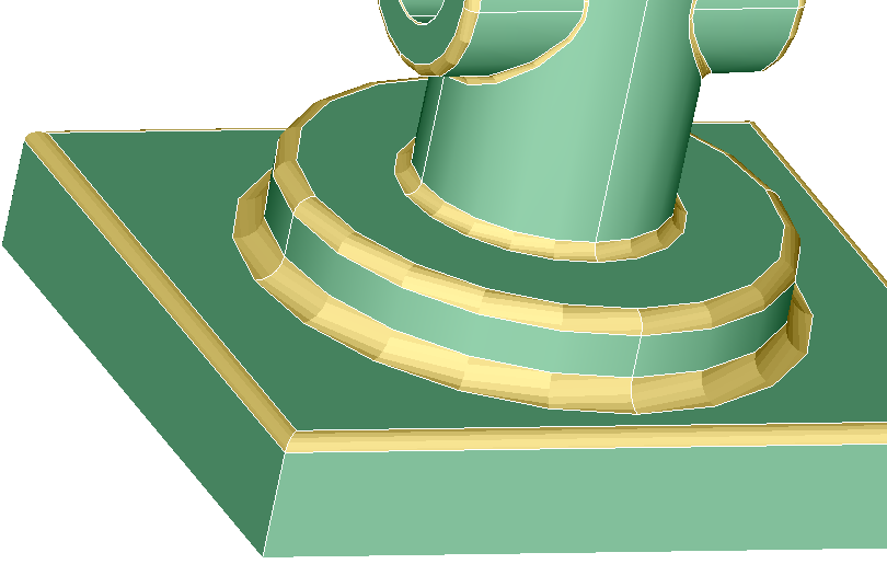
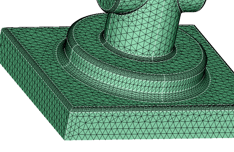
Body is meshed with the global mesh size and the following output shows the effect of fillet faces.
Merge tiny fillets
When this option is turned ON, fillets having only one element along its length (i.e., length along the fillet) are considered as tiny fillets and will be merged with the adjacent fillet.
Example 2
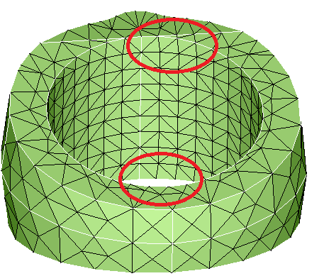
Input CAD model contains the tiny fillets for selected faces as shown below.
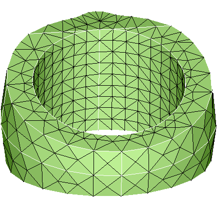
After applying the mesh control by using merge tiny fillet option. The mesher merges the tiny fillets for the faces as shown below.
Retain Mesh Flow on the Boundary
If "Retain Mesh Flow on the Boundary" toggle is turned ON the mesher will force the fillet faces to isomesh. This fillet special case will be used in meshing crank bore faces in engine block and for connecting rod special cases.
Example 3
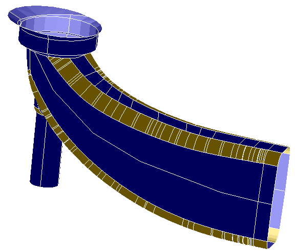
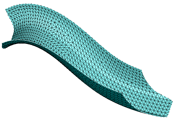
Fillet mesh control is applied to the set of selected faces. Retain Mesh Flow on the Boundary OFF.
Retain Mesh Flow on the Boundary ON.
Capture non-uniform curvature
Capture non-uniform curvature toggle is used to capture the concentrated local curvature by adding more layers.
Example 4
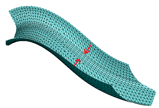
Output mesh with Capture non-uniform curvature toggle turned OFF.
Output mesh with Capture non-uniform curvature toggle turned ON. Extra layers of elements are added to capture the curvature locally.
- Fillets with fillet mesh control that are partially inside the region mesh control will be iso meshed with the size specified in the fillet mesh control or region mesh control whichever is minimum.
- In case the Number of elements for uniform curvature option is given as input, number of elements created along the curvature will be adjusted such that the element size will not to go below 20 % of Average size along fillet length.