Boundary Layer
Introduction
Boundary layer mesh control is used to control the number of layers on the selected local FEM faces.
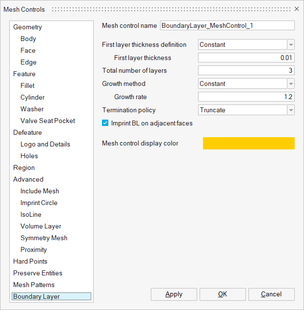
Boundary layer parameters
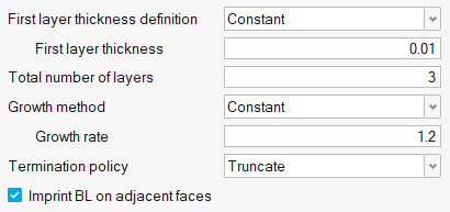
First layer thickness definition
First layer thickness can be controlled by using any one of the following two methods,
- Constant: Constant thickness will be maintained on the entire first layer.
- Fraction of Surface Mesh Size: The first layer height for each element equals the average element size multiplied by the given factor. This option is useful when the mesh size of 2D elements varies significantly and a constant first layer height is not needed. A smooth BL to tetra mesh transition for all elements can be achieved by using this option.
Total number of layers
Determines the total number of layers to be created.
Growth Rate
Layer height transition between each layer will be controlled by Growth Rate.
Growth Method
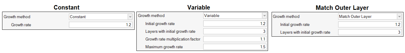
- Constant: This will determine boundary layer growth based on a constant ratio such as growth rate.
- Variable: This will be used to define the growth of BL beyond certain number of layers. An initial growth rate and number of layers with initial growth rate must be defined. In above settings, by default, the first three boundary layers grow based on initial growth rate described above. However, subsequent layers grow by the growth rate multiplied by the Growth rate multiplication factor. Thus, if t is the initial thickness, r is the initial growth rate, and a is the growth rate multiplication factor, then the thicknesses of the successive layers are t, t*r, t*r*(r*a), t*r*(r*a)^2, and so on. This option acts as a growth rate on the growth rate, but only after the first few initial boundary layers.
- Match Outer Layer: First few layers from the wall grow based on growth rate and remaining layers will be adjusted such that the final BL size matches with the core volume mesh size. This method helps to obtain a smoother transition from boundary layer mesh to volume mesh.
Termination policy
Determines what to do when BL has reached the defined criteria such as layer thickness and growth rate.
- Truncate: This helps to chop off the BL if elements reach the aspect ratio criteria.
- Squeeze: It allows the BL to grow until the neighbouring elements begin to grow, even if elements reach the aspect ratio criteria with GR =1.
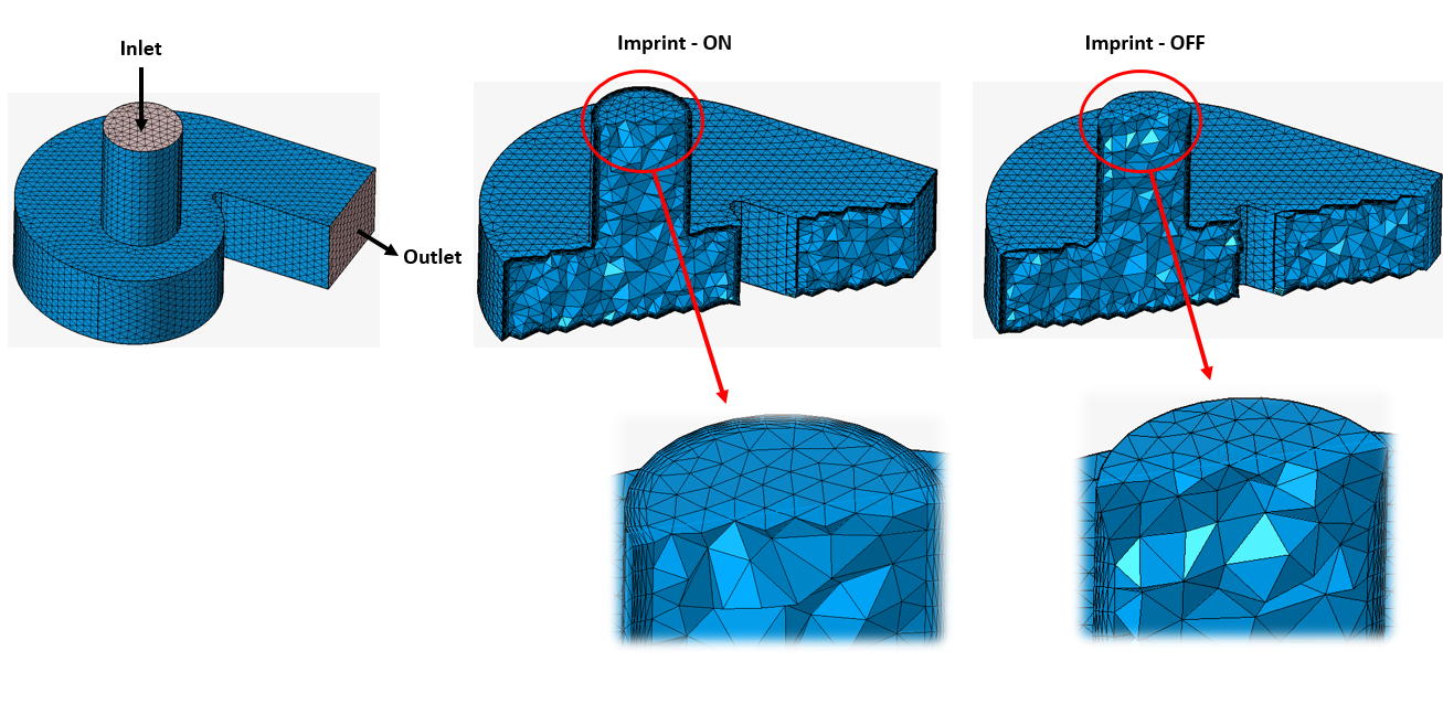
Imprint BL on adjacent faces
- ON: It allows mesh modification in No BL surfaces. Boundary layers will be imprinted on these adjacent No BL surfaces.
- OFF: Prevents the modification of boundary elements in No BL surfaces.
In below example, inlet and outlet are No BL faces:
Note:
- BL mesh control is supported only for FE input.
- After applying mesh control, “CFD Mesh” option from “Mesh – 3D Mesh – CFD” have to be used to generate the BL mesh.