Face Mesh Control
Introduction
Face Mesh Control is used to control the mesh on the selected local faces. A uniform mesh is generated on the face that has the face mesh control specified. The curvature is ignored.
Average Element Size (AES)
The mesh generated for this local region will have elements with edge lengths that fall between AES*Sqrt(2) and AES/Sqrt(2).
Merge Selected Faces
Selected local faces will be merged in to a single face when Merge option is enabled.
Layers
- Number of layers
Number of layers required along the thickness of the surface can be controlled by AES. But when there are faces with different thickness, it becomes difficult to control the number of layers of elements using the AES. For such cases, Layers option is used to specify the minimum number of layers required along the thickness. This is supported only for CAD inputs.
If the number of layers did not satisfy the user given minimum element size, then the number of layers will be reduced to satisfy the minimum element size.
- Uniform
In the regions where layers are introduced, the ratio of the element length along the thickness of the face and the element length along the longest direction will vary between 1.25 to 1.5.
- Stretched
In the regions where layers are introduced, the length of the element will be adjusted based on the Aspect Ratio given i.e the ratio of the element length along the thickness of the face and the element length along the longest direction will be less than the Aspect ratio given
Use rest of the parameters from Global
Use rest of the parameters from Global option is used to modify the values of Minimum Element Size,Aspect Ratio,Maximum Angle Per Element,Curvature Minimum Element Size and Surface Mesh grading.
- Minimum Element Size
The mesh will have no elements with an edge length smaller than the Minimum Element Size.
-
Geometry Approximation
- Maximum Angle Per Element: The approximation of a geometry is related to the angle made by an element edge on a perfect circle. Suppose the angle is 45 deg, then this will approximate a circle by 8 elements. This same measure is extended to an arbitrary curved surface.
- Curvature Minimum Element Size: The mesh approximates the geometry by varying the mesh size as a function of the curvature. Such geometry approximation cannot result in a mesh size smaller than Curvature Minimum Element Size.
- Surface Mesh Quality
- Aspect Ratio: Aspect ratio determines the quality of mesh. Aspect Ratio value varies from 1(equilateral element) to infinity(flat element). The default aspect ratio value is 10.
- Mesh Grading: The variation of the mesh in the face from the boundary to the interior is controlled by the Surface Mesh Grading. Default Surface Mesh Grading value is 1.5. (Average Element size marches 1.5 times from fine to coarse).
Example 1
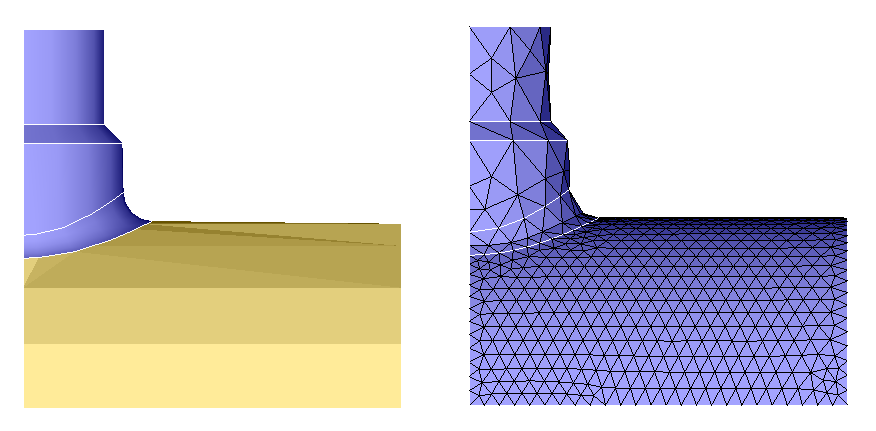
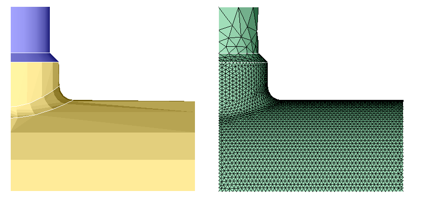
Face mesh control is applied with an average element size of 1 for a face.
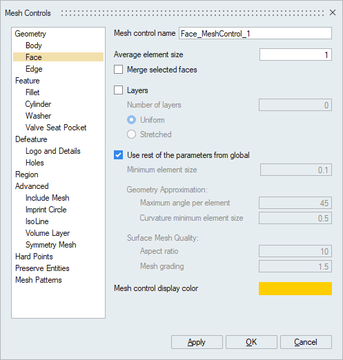
The body is meshed with global mesh control size of 3 and the following figure shows the local face having a mesh size of 1.
Example 2
Face mesh control with Merge option ON and average element size of 0.5 is applied for three faces.
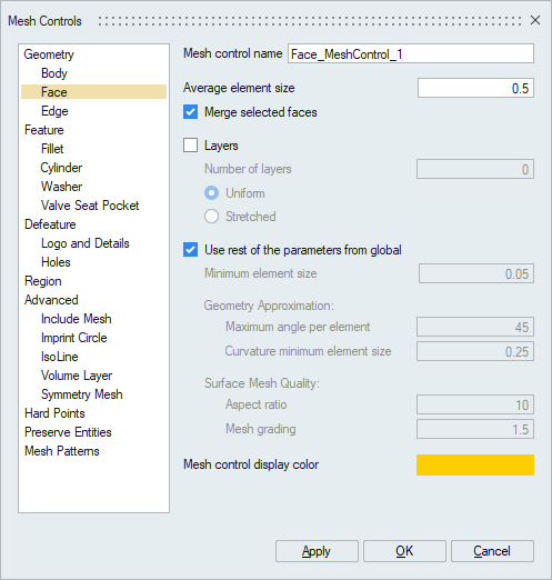
Three faces are merged and they have a mesh size of 0.5.
Example 3
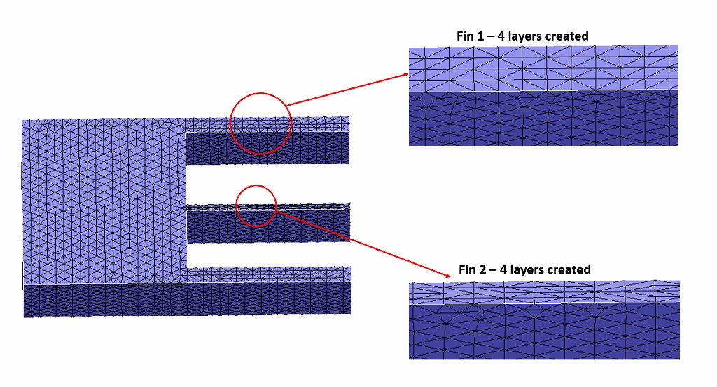
Face mesh control with Layer option ON and number of layers is given as 4 with Uniform option.
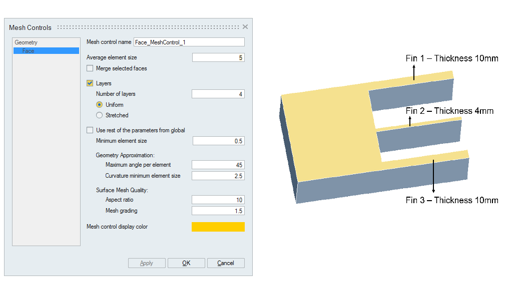
In the Fin 1 and Fin 2 regions, 4 layers of elements are created with ratio of element height along the thickness of face and length of the element are within 1.25.
Example 4
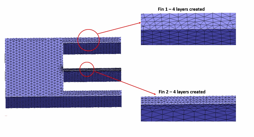
Face mesh control with Layer option ON and number of layers is given as 4 with Stretched option.
In the Fin 1 and Fin 2 regions, 4 layers of elements are created with ratio of element height along the thickness of face and length of the element are created such that the Aspect ratio is satisfied.
Example 5
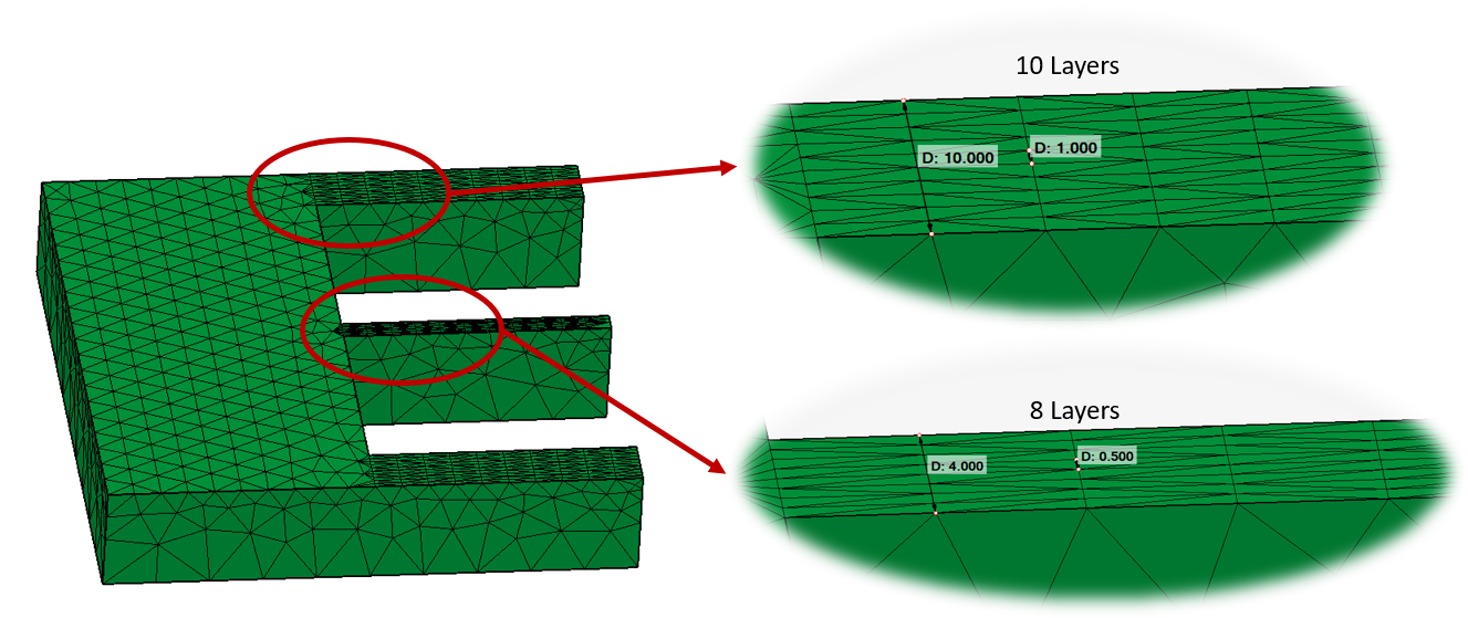
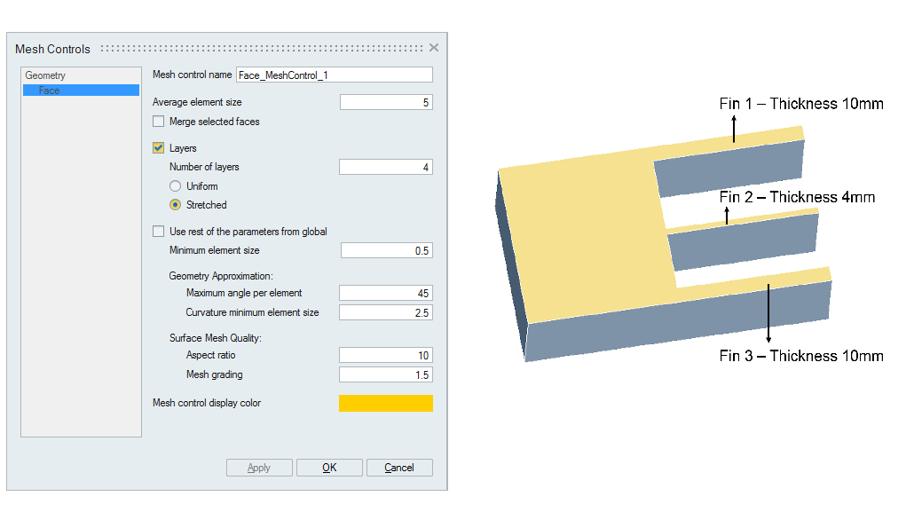
Face mesh control with Layer option ON and number of layers is given as 10 with Stretched option.
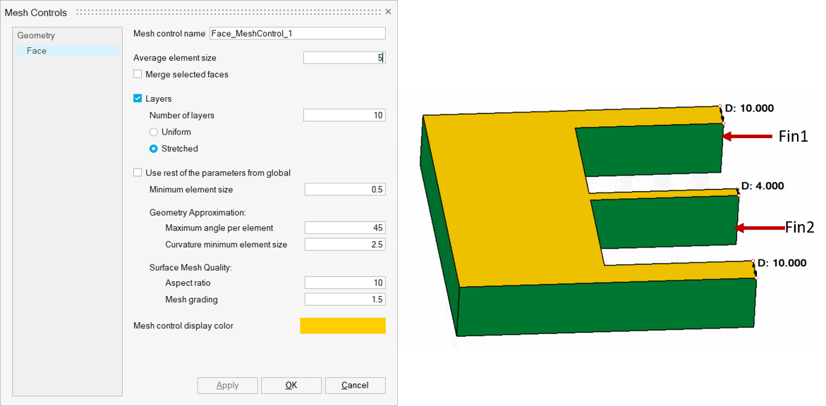
The thickness of fin 1 is 10mm. When 10 layers of elements are introduced, the height of each element is 1mm. This satisfies the minimum element size of 0.5mm and 10 layers of elements are created.
But the thickness of the fin 2 is 4mm. When 10 layers of elements are introduced, the height of each element will be 0.4mm, which does not satisfy the minimum element size of 0.5mm. Therefore, the number of layers on fin 2 is reduced to 8, with each layer of size 0.5mm which will satisfy the minimum element size criteria.