Cylinder Mesh Control
Introduction
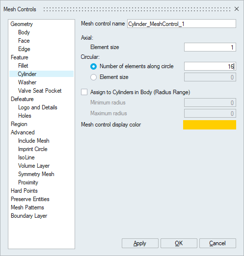
Cylinder Mesh Control is used to control the mesh in both axial and circular direction on the selected cylindrical surfaces.
- Axial
Axial element size is used to control the element size along the length of the cylindrical faces.
- Circular
Number of elements or element size is used to control the number of mesh seeds/element size along circular direction.
- Assign to Cylinders in Body(Radius Range)
This option is used to apply the cylinder mesh control to a body. The cylindrical surfaces within the specified minimum and maximum radius range in the selected body will have the cylinder mesh control applied to them. Using Right Click | Select Features, the list of faces for which the cylinder mesh control will be applied can be cross-checked.
Example 1
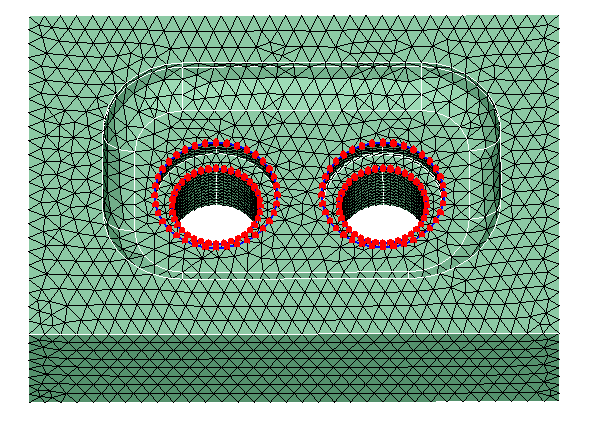
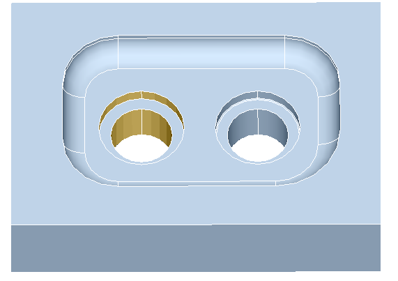
Cylinder mesh control is applied to the highlighted cylindrical faces with axial mesh size of 2 and circular mesh seeds as 36.
The body is meshed with global mesh size of 6 and the following figure shows the variation between cylindrical faces with and without the cylindrical mesh control.
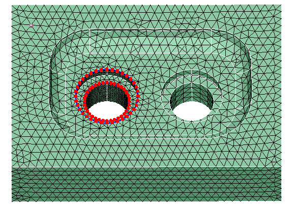
Example 2
In addition to applying the cylinder mesh control on selected faces, it can also be applied to body, where all the cylinders within the given radius range are selected for applying the mesh control. Following example shows the output from body based cylindrical mesh control.