Symmetry Mesh
Introduction
This option is used to get identical mesh between two identical faces\edges ("from" and "to" face\edge). In face-based symmetry mesh if there are any discontinuous edges between face, then we need to pick three nodes/vertices in an order for both "from" and "to" face.Multiple "from" and "to" faces\edges are supported. For each face\edge pair, separate mesh control will be created. The order in which the "from" and "to" faces\edges are selected should be consistent.
 Angular symmetry
When master and slave faces\edges are symmetric about an axis, whether they are connected or not, Angular symmetry option helps us to identify the symmetry face\edge pairs. Angular symmetry option helps us to identify the symmetry face\edge pairs even if they are not connected. When selecting multiple "from" and "to" faces\edges, the order of selection is not a concern.
Coplanar face selection
To enable easy selection of coplanar faces in the model, we could select one or more planar face and click on the “Select Coplanar faces” button.
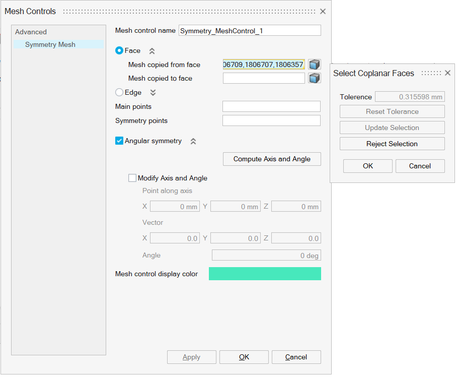
After selecting the reference planar face(s) as input and on the "Select Coplanar faces" button, the “Select Coplanar Faces” dialog will pop up and the corresponding coplanar faces will be automatically identified using the tolerance value.
On “Reject Selection” in the “Select Coplanar faces” dialog, the identified co-planar faces will be ignored, and the “Tolerance”, “Reset Tolerance”, and “Update Selection” will be enabled. On “Update Selection”, the corresponding coplanar faces will be automatically identified for the specified tolerance.
“Reset Tolerance” will reset the tolerance to the initially computed value.
Collinear edge selection
To enable easy selection of collinear edges in the model, we could select one or more linear edges and click on the “Select collinear edges” button. This will select all the collinear edges with respect to the previously selected edges.
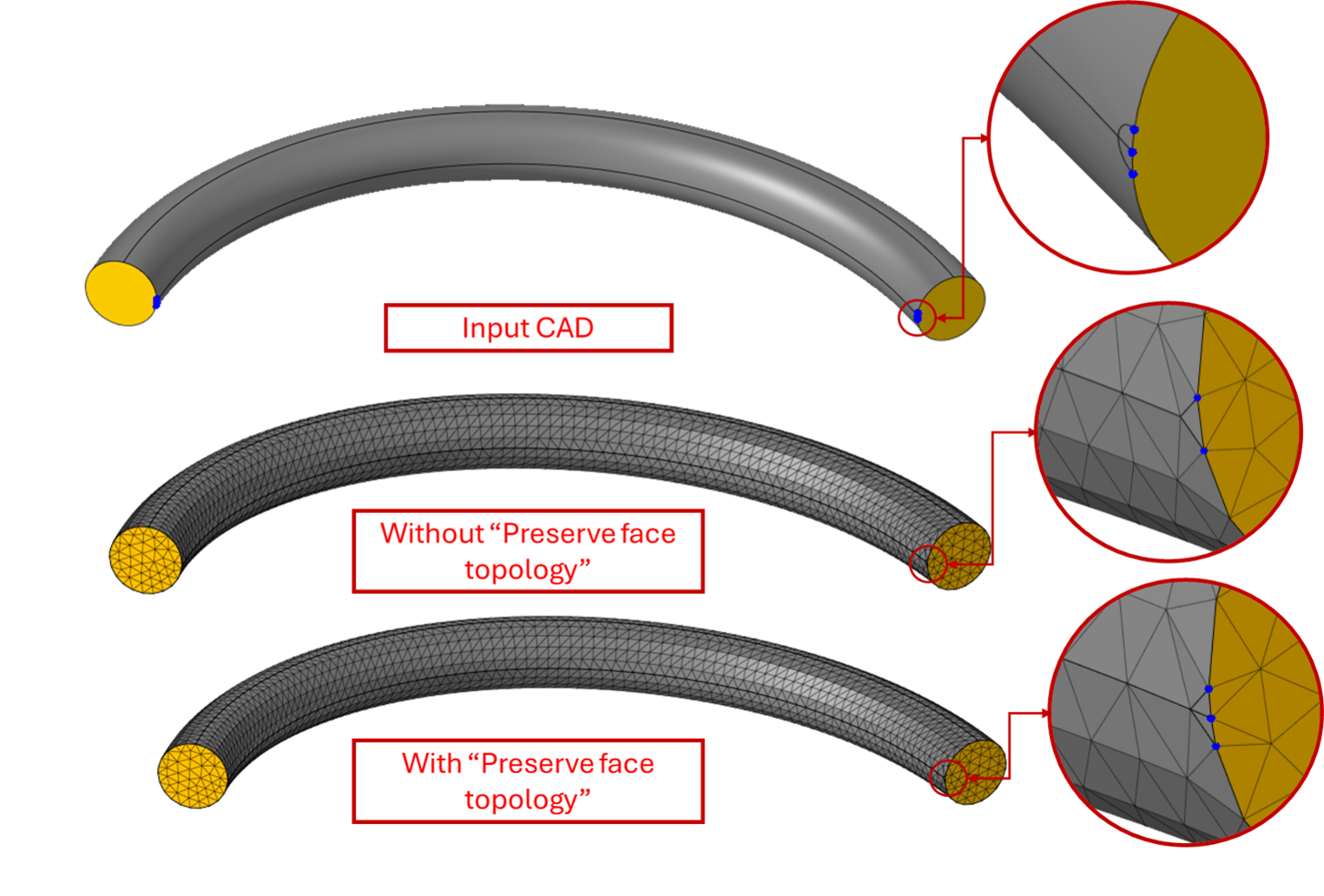
Preserve Face Topology
Enable this option to retain all edges on a face during the meshing process. When activated, even small or narrow edges are preserved, preventing the face vertices from collapsing or being simplified. This is especially useful when fine geometric details are essential for accurate simulation results.
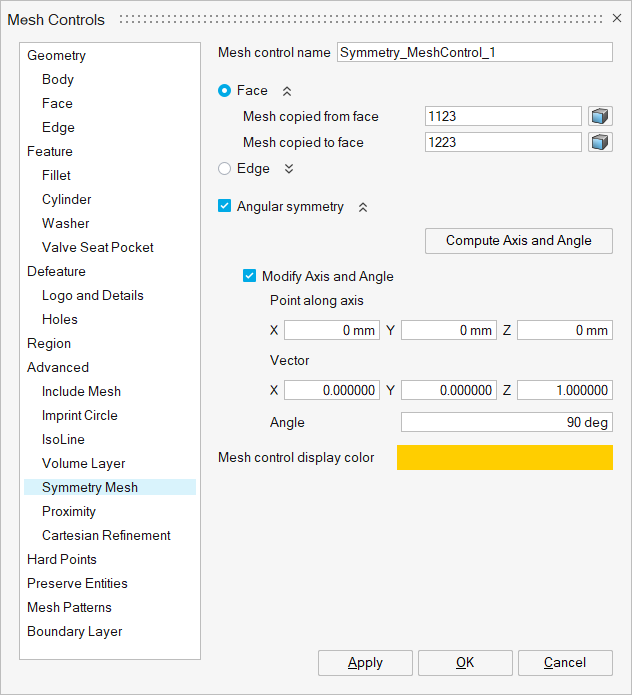
Compute axis and angle
This option enables the user to view the internally computed axis (in terms of point and vector) and angle between the “from” face\edge and “to” face\edge, which are identified as angular symmetric pairs. Compute is possible only when the individual input (“from” and “to”) faces\edges are coplanar\collinear. It is enabled only when angular symmetry option is turned ON.
Modify axis and angle
This option enables the user to modify the internally computed axis and angle. The Mesher will be forced to use these values in surface mesh. It is enabled only when angular symmetry option is turned ON.
- Angular symmetry mesh control could be applied for faces\edges from different CAD Parasolid bodies in a model. However, the symmetry mesh control would be respected only when Surface Mesh / Tet Mesh is done with “Create matching mesh (Parasolid)” toggle turned ON.
- In mesh specifications export, symmetry mesh control with the faces\edges from different bodies are not supported.
- If all the bodies with symmetry mesh control are transformed or any CAD operations are carried out and if the “Modify Axis and Angle” check box is ON, the values of “Point along axis”, “Vector”, “Angle” will be automatically updated for CAD input.
- During CAD operation or transformation if the geometry (input faces\edges) is modified, internally the symmetry mesh control is validated and deleted if input becomes invalid.
- Symmetry mesh control is not supported for Quad mesh.
Example
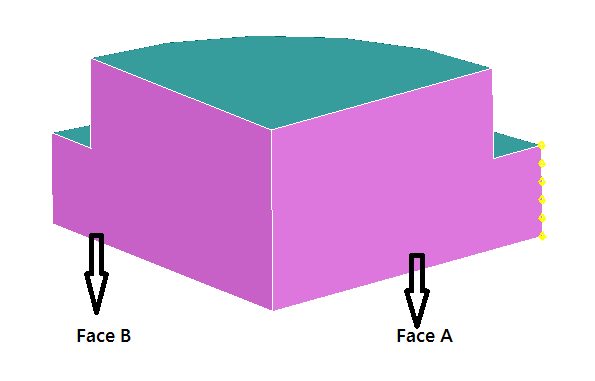
Case 1: Face based symmetry mesh control
Symmetry mesh is applied to the highlighted faces, such that the mesh from Face A is to be copied to the Face B. An edge mesh control is also applied along Face A to clearly show that the mesh in both the faces are identical.
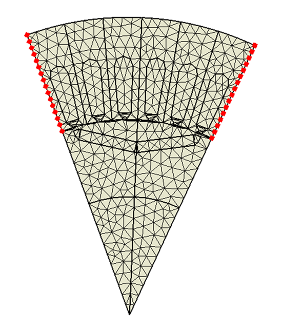
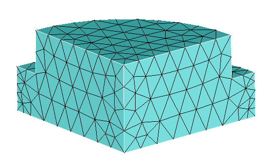
Output
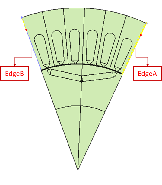
Case 2: Edge based symmetry mesh control
Symmetry mesh is applied to the highlighted edges, such that the mesh from edge A is to be copied to the edge B. An edge mesh control (Bias seeding) is also applied along edge A to clearly show that the mesh in both the edges are identical.