Edge Mesh Control
Introduction
The mesh on an edge is controlled using the Edge mesh control.
Two edge mesh controls are available:
- Uniform Seeding
- Bias Seeding
Uniform Seeding
Edge Seeds are applied either by specifying the average element size or by specifying the number of elements.
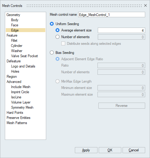
In case of edges that forms a circle (or a part of a circle), the seeds can be distributed using “Distribute seeds along selected edges” option. This option is made available only when the “No of Elements” option is used.
Bias Seeding
Bias Seeding is used to seed an edge such that a constant ratio is maintained between adjacent bar elements. Edge Length will be in the following series: Lmin, Lmin * r, Lmin * r * r, . . . where Lmin is the minimum edge length and r is the ratio.
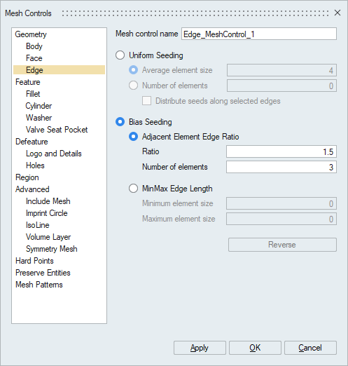
Bias seeding is applied either by specifying
- The Ratio and the number of elements, or
- The minimum element length and maximum element length.
For Bias Seed, the user has to select an edge and the direction of seeding. When an edge is selected, the direction of seeding is indicated by an arrow. It could be changed using Reverse option
Examples
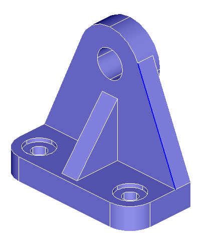
Edge mesh Control: Using Average Element Size
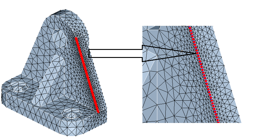
Edge mesh control is applied to the highlighted edge using average element size as 1. (length of the edge is 60)
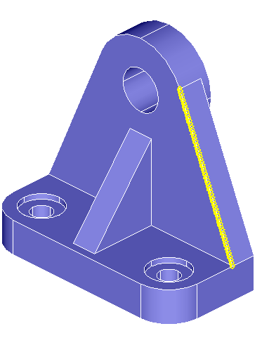
Seeds will be created for the selected edge, as shown below.
The body is meshed with a global mesh size of 6 and the output mesh is shown below.
Edge Mesh Control: Using Number of Elements
For the same highlighted edge, when edge mesh control is applied using the number of elements as 60, we would be getting the same output.
Edge Mesh Control: Number of Elements with Distribute Seeds
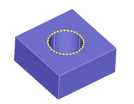
When the user knows the total number of elements for a list of edges, then the Distribute Seed option comes in handy. This can be best illustrated using the case of a circle formed by 4 edges, as shown below. The user need not apply egde mesh controls to each edge. Instead, the 4 edges can be selected and the total number of elements, say 32, can be given as input with the Distribute Seed option enabled. Hence, for each edge 8 elements are assigned as shown below.
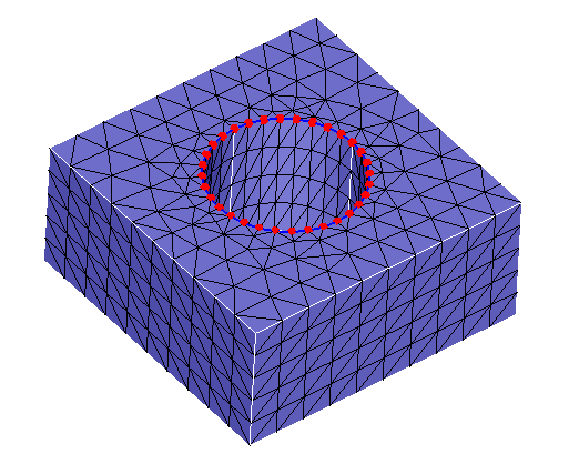
The body is meshed with a global mesh size of 1 and the output mesh is shown below.
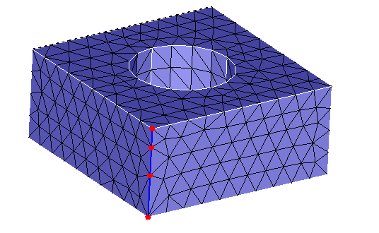
Edge Mesh Control: Using Biased Seed – Ratio and Number of elements
As briefed above, the biased seed option enables seeding an edge such that a constant ratio is maintained between adjacent bar elements.
For an edge of length 4.5, when Ratio = 1.5 and Number of Elements = 3 is used, the lengths of the bar elements will be, .947, 1.421 and 2.132, as shown below.
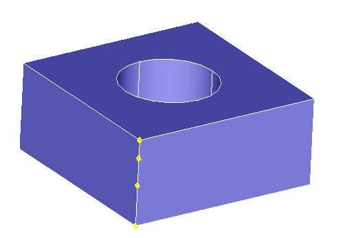
The body is meshed with a global mesh size of 1 and the impact of the edge mesh control is shown below.
Edge Mesh Control: Using Biased Seed – Minimum and Maximum edge length
This option is used in the case where the minimum and maximum element sizes are known. For the above example, if the minimum element size and maximum element size are specified as .9 and 2.1, the bar elements sizes will be .9, 1.35 and 2.25. There will be slight deviation in the last bar element to accommodate the total edge length.