Region Mesh Control
Introduction
Region mesh control applies the local refinement within the defined shape (cuboid/cylinder/sphere) of region. Also, it can break the face/body along the boundary of the chosen shape (cuboid/cylinder/plane/cone).

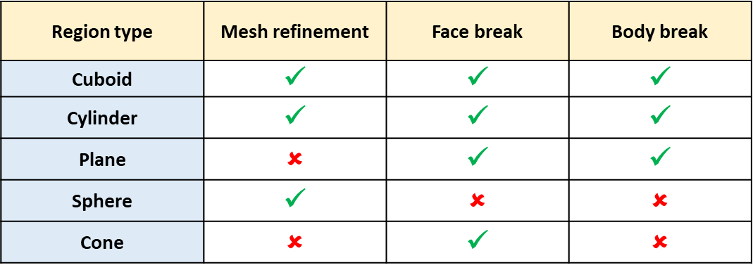
Below table describes the break and refinement support of various region types.
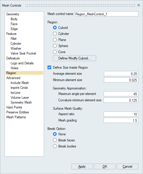
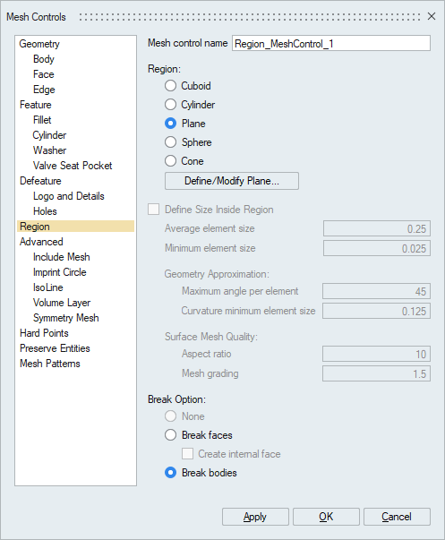
Define Size Inside Region
Define size inside region enables user to input user defined mesh parameters for meshing inside the region.
- Average Element Size (AES):
The mesh generated for this local region will have elements with edge lengths that fall between AES*Sqrt(2) and AES/Sqrt(2).
- Minimum Element Size:
The mesh will have no elements with an edge length smaller than the Minimum Element Size.
- Maximum Angle Per Element:
The approximation of a geometry is related to the angle made by an element edge on a perfect circle. Suppose the angle is 45 deg, then this will approximate a circle by 8 elements. This same measure is extended to an arbitrary curved surface.
- Curvature Minimum Element Size:
The mesh approximates the geometry by varying the mesh size as a function of the curvature. Such geometry approximation cannot result in a mesh size smaller than Curvature Minimum Element Size.
- Aspect Ratio:
Aspect ratio determines the quality of mesh. Aspect Ratio value varies from 1(equilateral element) to infinity (flat element). The default aspect ratio value is 10.
- Mesh Grading:
The variation of the mesh in the region from the boundary to the interior is controlled by the Surface Mesh Grading. Default Surface Mesh Grading value is 1.5. (Average Element size marches 1.5 times from fine to coarse).
- Break Option
The size and break options can be applied together for cuboid and cylinder type whereas for the plane and cone type, break option alone is valid and for sphere type, only size option is valid. If break is applied on the body, the new bodies are created.
In plane type, both infinite and finite plane can be defined. For infinite plane, both body break and face break option can be applied. For finite plane, only face break can be applied. For Break face, option to create internal face is supported.
The basic idea is to assign the specified size for the entities (faces/edges) that are lying inside the region (cylinder/cuboid/sphere). Entities which are partially inside the region will be graded according to region of overlap.
In modify mode, Region's options are editable
Cuboid Region
Example 1
- Select the region type as cuboid
- Choose define/modify and specify the box on particular region
- Select the break type as none
- Enter the mesh parameters
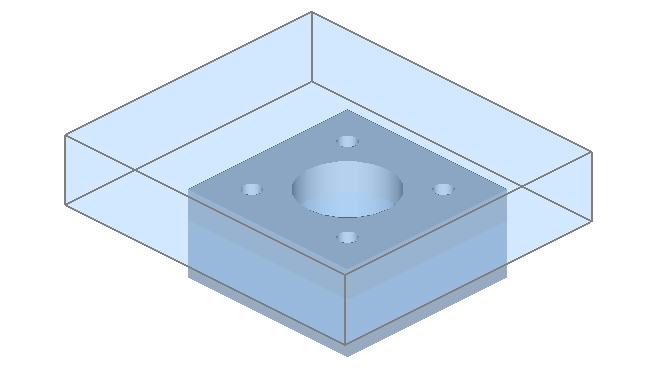
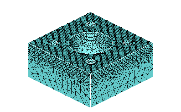
- Mesh is created inside the cuboid with respect to the given mesh
parameters.
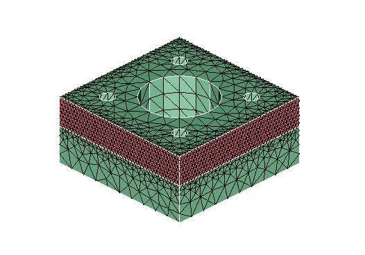
Example 2
- Select the region type as cuboid
- Choose define/modify and specify the box on particular region
- Select the break type as face and choose the faces to break
- Enter the mesh parameters
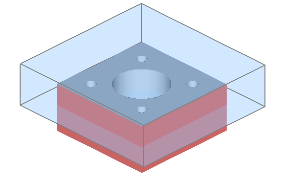
- Mesh is created inside the cuboid with respect to the given mesh parameters and
the faces are broken.
Cylinder Region
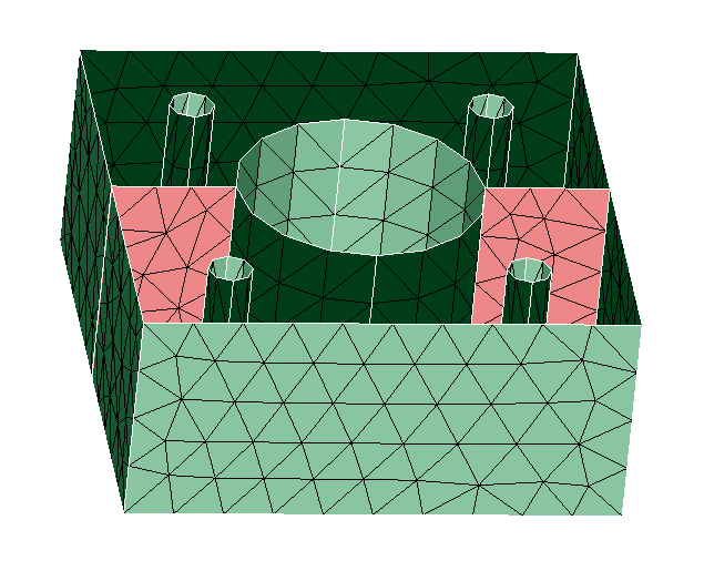
Example 1 - Local Size in Cylindrical Region
- Select the region type as cylinder
- Choose define/modify and specify the cylinder on the particular region
- Select the break type as none
- Enter the mesh parameters
- Mesh is created on the region lying inside the cylinder with respect to the
given mesh parameters.
Example 2 - Local Size with Face Break in Cylindrical Region
- Select the region type as cylinder
- Choose define/modify and specify the cylinder on the particular region
- Select the break type as face and choose the faces to break
- Enter the mesh parameters
- Mesh is created on the region lying inside the cylinder with respect to the
given mesh parameters and the faces are broken.
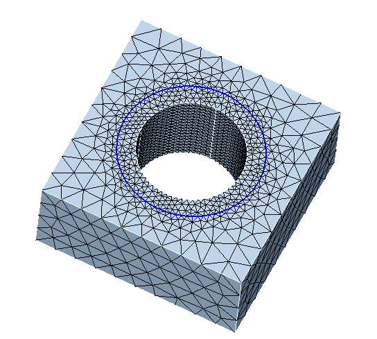
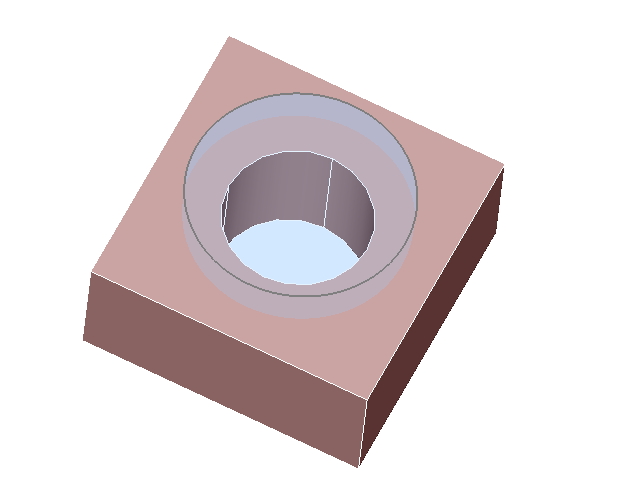
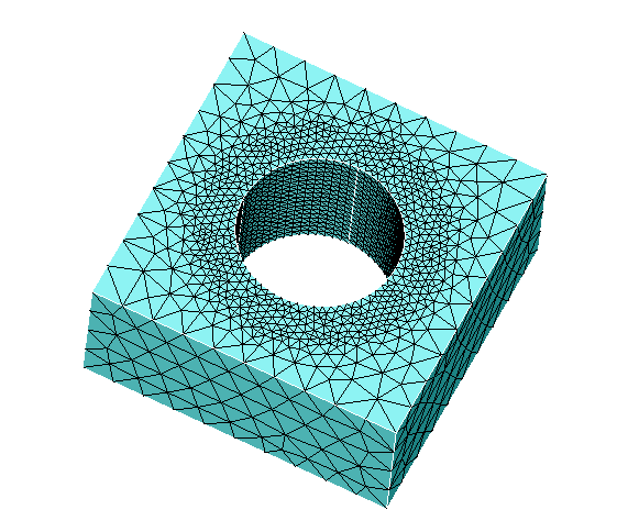
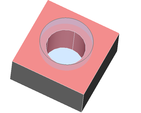
Example 3 - Local Size in Hollow Cylindrical Region
- Select the region type as cylinder
- Choose define/modify and specify the cylinder on the particular region with
hollow option and setting the appropriate inner and outer radius
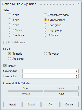
- By default, the size is taken and breaking won't have any effect with this option
- Enter the mesh parameters
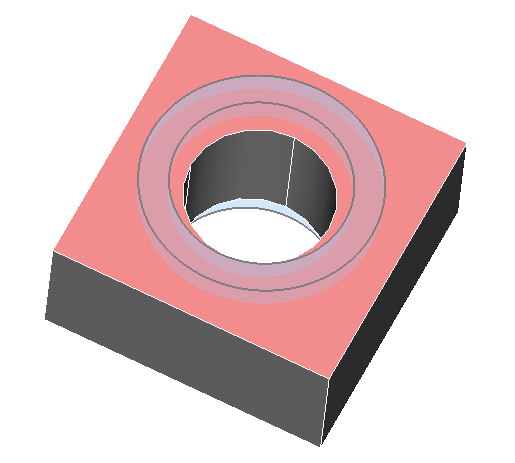
- Mesh is created on the region lying between the inner and outer radius of the
cylinder with respect to the given mesh parameters.
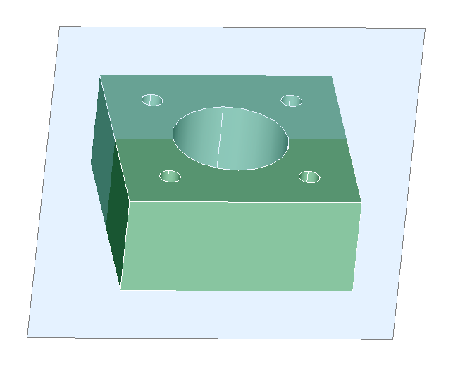
Plane Region
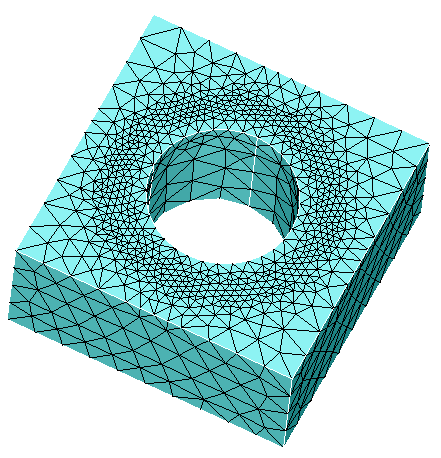
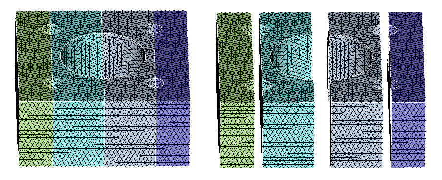
Example 1 - Plane body break
- Select the region type as plane
- Choose define/modify and specify the plane
- Select the break type as body and select the body
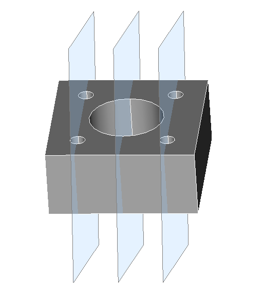
- After meshing body gets break on the specified plane location
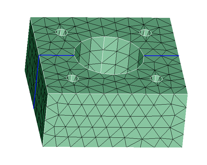
Example 2 - Plane face break
- Select the region type as plane
- Choose define/modify and specify the plane
- Select the break type as face and select the body
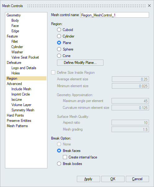
- After meshing, face of the body gets break on the specified plane location (See
new edges marked in blue)
Example 3 - Plane face break with Create internal face
- Select the region type as plane
- Choose define/modify and specify the plane
- Select the break type as face and select the body. Enable the toggle "Create
internal face"
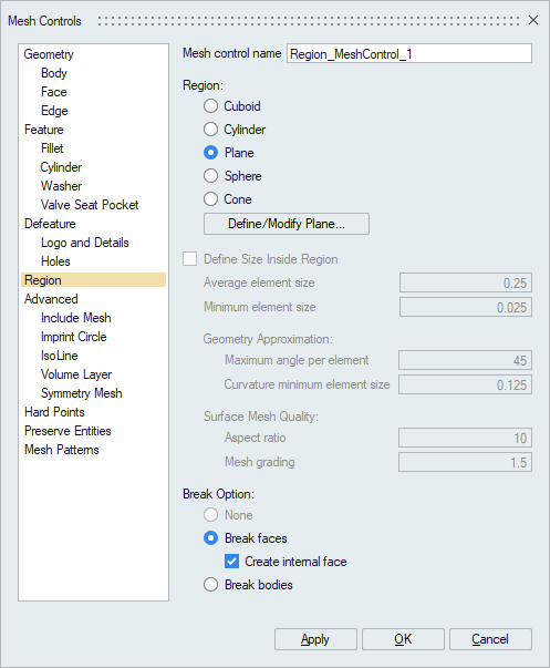

- After meshing, face of the body gets break on the specified plane location and
internal faces are created along the plane(See internal faces are
selected)
Cone Region
Refer the following link to view the demo for creating circular array of cones. Region mesh control : Cone Demo
- Direct TET mesh on a CAD body with region mesh control will only break the faces and it will not break the body. The element size set in region mesh control will be respected by both surface and internal elements.
- TET mesh on a FEM body with region mesh control will not break any faces or body. The element size set in region mesh control will be respected only by the internal elements.