Start Point Determination - Meshing
Introduction
Assemblies are made of parts which typically are meshed separately. Once the meshed parts are assembled, it is important for the mesh on the parts are aligned. To enable the matching of mesh between parts of an assembly modeling rules are defined and followed. Also, within each part, it is possible to have cylindrical features that have the same axis but the start point for the circular division need not be aligned. Here again, a mesh that is aligned in the circular direction for all cylinders that have the same axis is desired. Features of interest are cylindrical surfaces present in bolt holes, liners, journals, pins, etc. The start point is defined with respect to the axis of the cylinder and the global coordinate system.
The rule used to define the start point for the circular division is explained below:
| CASE | AXIS DEFINITION | START POINT |
|---|---|---|
| 1 | Axis is parallel to X - Axis | Positive Y |
| 2 | Axis is parallel to Y - Axis | Positive Z |
| 3 | Axis is parallel to Z - Axis | Positive X |
| 4 | Axis is parallel to XY - Plane | Positive Z |
| 5 | Axis is parallel to YZ - Plane | Positive X |
| 6 | Axis is parallel to ZX - Plane | Positive Y |
| 7 | Axis lies on arbitrary plane | Closest principle plane to the axis is found and the corresponding start point is taken based on cases 4, 5 and 6. |
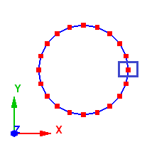
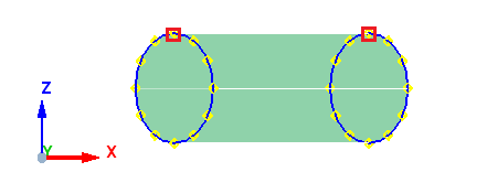
Case 1: Axis is parallel to X - Axis
When the axis is parallel to the X - axis, the start point of the meshing is taken from positive Y. In the example below, the axis is along the X - axis, thus the start point is taken from positive Y as shown below.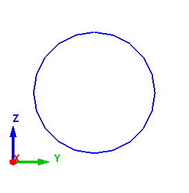
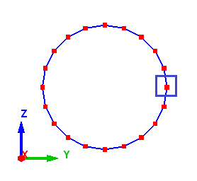
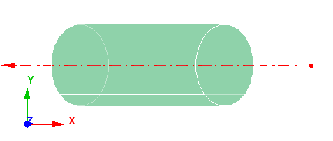
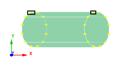
Case 2: Axis is parallel to Y - Axis
When the axis is parallel to the Y - axis, the start point of the meshing is taken from positive Z. In the example below, the axis is along the Y - axis, thus the start point is taken from positive Z as shown below.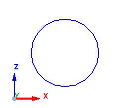
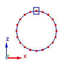
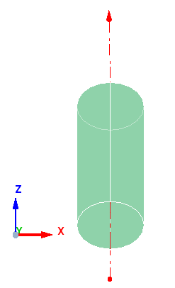
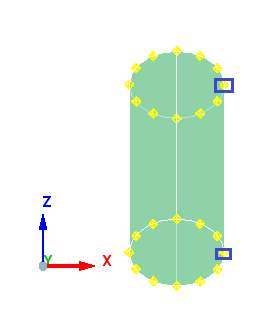
Case 3: Axis is parallel to Z - Axis
When the axis is parallel to the Z - axis, the start point of the meshing is taken from positive X. In the example below, the axis is along the Z - axis, thus the start point is taken from positive X as shown below.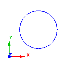
Case 4: Axis is parallel XY - Plane
When the axis is parallel to XY plane, the start point of the meshing is taken from positive Z. In the example below, the axis is lies on XY plane, thus the start point is taken from positive Z as shown below.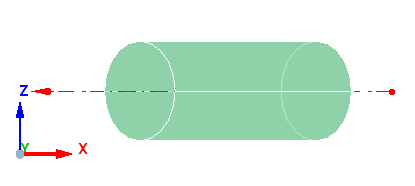
Case 5: Axis is parallel YZ - Plane
When the axis is parallel to YZ plane, the start point of the meshing is taken from positive X. In the example below, the axis is lies on YZ plane, thus the start point is taken from positive X as shown below.
Case 6: Axis is parallel ZX - Plane
When the axis is parallel to ZX plane, the start point of the meshing is taken from positive Y. In the example below, the axis is lies on ZX plane, thus the start point is taken from positive Y as shown below.
Case 7: Axis lies on arbitrary plane
When the axis lies on arbitrary plane, the angle made between the arbitrary plane and principle planes (XY, YZ & ZX) is computed and the principle plane with minimum angle to arbitrary plane is chosen and start point is selected based on the cases 4, 5 and 6.