Coil component
The following are the circuit components supported as of SimLab:
| Component | Icon | Description |
|---|---|---|
| Coil | FEM coupling components, orientation affects the computation. |
Introduction
The coil components are used to define the coupling between the circuit and FE domain. Apart from the usual line edit inputs, users need to select bodies from the FE domain to establish the coupling with the finite element analysis.
![]()
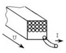
From the physical point of view, a stranded conductor consists of one or more thin wire elementary conductors. The diameter of the wire is lower than the skin depth, so that the current density is practically constant over all the conductor cross-section.
The basic relation linking the current I, the voltage U and the flux Φ is given below.
The current flowing through a stranded conductor component is the current I flowing through each strand (turn) of the correspondent coil.
The voltage at the terminals of a stranded conductor component is the voltage U at the terminals of the modeled assembly of the coil strands.

Where R is the resistance of the coil and phi is the flux passing through the coil.
The resistance R of a stranded component is equal to the resistance of the coil strands assembly:
R = n⋅R_strand = n⋅(ρ⋅l / S_strand)

The cross section of a strand is equal to:

- ρ: material resistivity
- l: length of a strand, viz. the depth of the modeled device in 2D
- F: space factor (0 < F < 1) (area of the surface filled by the strands / area of the modeled region surface)
- n: number of strands
Dialog box in MT2D
The dialog definition of the coil component looks as follows:
Additional resistance: defines the resistance of the coils specified by the user
Connection type: defines if the connection is series or parallel or user definition of number of conductor in parallel
Number of turns: defines the number of turns or strands in the coil.
Current orientation: Positive or negative. For 2D this is inside the plane or out of the plane.
Coil fill factor: Define the fill factor of the coil. Used in the computation of the coil losses and resistance calculations.
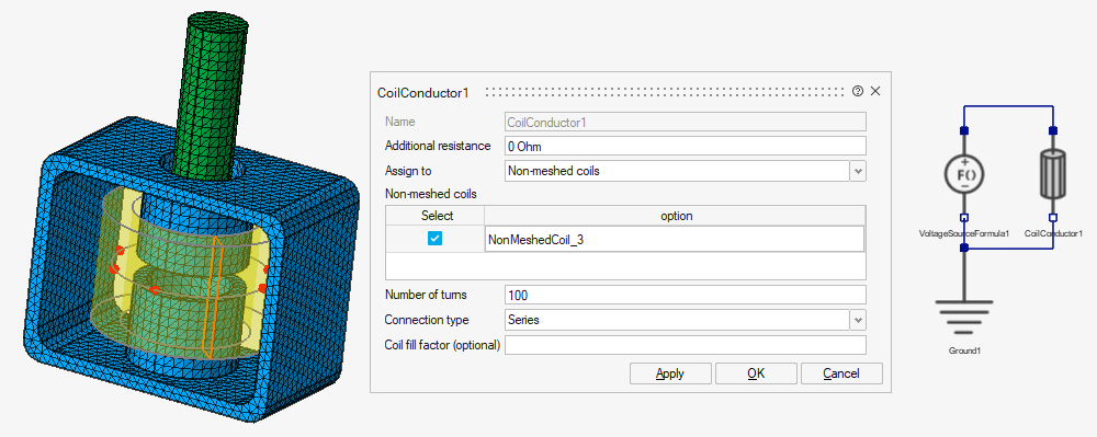
Dialog box in MT3D and MAC3D
The dialog definition of the coil component looks as follows:
Additional resistance: defines the resistance of the coils specified by the user
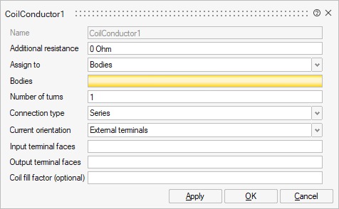
Assign to: the user have the choice between Bodies or Non-meshed coils
- Bodies: selection of body/bodies that represent the
coil in the FE domainNote: User should select only meshed bodies that are assigned to the current solution, else the solver will show an error.
- Non-meshed coils: selection of one or several non-meshed coils that represent analytic coil.
Number of turns: defines the number of turns or strands in the coil.
Connection type: defines if the connection is series or parallel or user definition of number of conductor in parallel
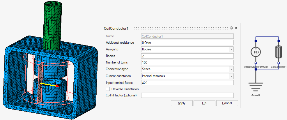
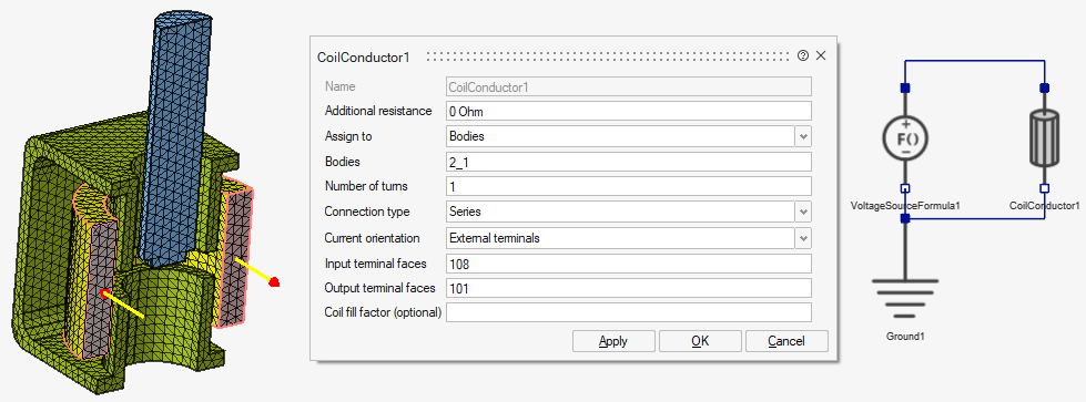
Current orientation (only for body assignment): User have the choice between External terminals or Internal terminals to define the direction of the current.
- External terminals, the user should select :
- the Input terminal faces
- the Output terminal faces
- Internal terminals, the user should select only the Input terminal faces. It is possible then to reverse the orientation with Reverse Orientation.
Coil fill factor: Define the fill factor of the coil. Used in the computation of the coil losses and resistance calculations.
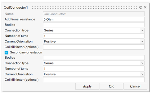
users have the option to define a secondary orientation for the coil component if required. This can be activated by clicking on the checkbox Secondary orientation.
3D use case:
- Assign to bodies - internal terminals
- Assign to bodies - externals terminals
- Assign to non-meshed coils
the coil component is not assign to a body, but to a Non-meshed coil LBC.